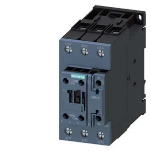
Siemens 3RT2035-1XB40-0LA2 — SIRIUS Size S2 Contactor, 24 VDC Coil
It carries a 24 VDC coil with screw-type terminals and is rated for main contact currents of 40 A at 480 V and 41 A at 600 V — figures that govern its suitability for motor circuits up to 7.5 hp at 230 V. The 24 VDC coil draws an inrush peak of 3 A and holds with a pick-up/drop-out ratio of 0.7 of rated voltage. The contactor mounts via screw or snap-on onto 35 mm standard mounting rail per DIN EN 60715, and its mounting position allows ±180° rotation on a vertical surface plus ±22.5° tilt forward/backward — useful when fitting into tight enclosures.
The main contact ratings at 480 V (40 A) and 600 V (41 A) are the numbers that decide whether this contactor carries your motor load. The 40 A at 480 V figure is the AC-3 duty rating — the current it can switch motor loads under starting and running conditions. The 41 A at 600 V extends that capability into 600 V class panels common in North American installations. Auxiliary contact switching capacity is specified across multiple DC voltage levels: 10 A at 24 VDC, 2 A at 48 V and 60 V, 1 A at 110 V, 0.9 A at 125 V, 0.3 A at 220 V, and 3 A at 400 V. These ratings define the maximum DC current the auxiliary contacts can break at each voltage — critical when the contactor is used in a DC control circuit or interposing relay scheme. Includes an auxiliary switch. Mechanical life typical of 10,000,000 operations.
Panel Integration and Clearance
Physical dimensions: 114 mm height, 55 mm width, 130 mm depth. The 55 mm width is the DIN-rail footprint — it occupies three standard 18 mm module positions on a 35 mm rail. These clearances must be maintained for heat dissipation and arc containment. Wire termination: screw-type terminals accept 2x (0.5 to 1.5 mm²) or 2x (0.75 to 2.5 mm²) solid or stranded conductors. Maximum switching frequency at AC-4 duty is 300 operations per hour.