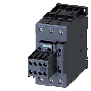
It carries a 110 VDC coil with spring-type terminals, rated for continuous duty. The main contacts are rated 40 A at 480 V and 41 A at 600 V, with a 7.5 hp rating at 230 V.
The 40 A rating at 480 V and 41 A at 600 V are the continuous current ratings for the main contacts — these define the maximum load the contactor can carry without overheating. For motor starting (AC-3 duty), you'd typically derate; the AC-4 maximum switching frequency is 300 operations per hour, which tells you this contactor isn't meant for high-cycle jogging or plugging applications. The 110 VDC coil draws an inrush peak of 1.5 A, which matters for control transformer sizing and DC power supply selection. The coil hold-in is sustained at the rated 110 VDC; dropout voltage is typically around 70% of rated (77 VDC) — ensure your control voltage doesn't sag below that during line starts.
Mechanical and electrical endurance
Arcing time is 10 to 20 ms at DC, and the contactor is designed for a DC switching range of 30 to 55 ms — this is the time the coil takes to pick up or drop out, affecting timing in safety circuits or sequential logic.
Dimensions are 114 mm height, 55 mm width, 178 mm depth. The width — 55 mm — is the key panel-space figure; it occupies one standard 55 mm-wide slot on a DIN rail.