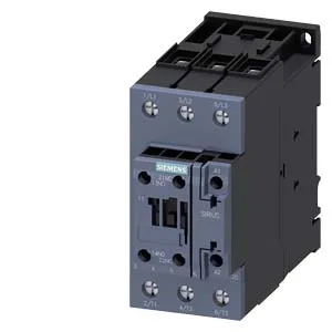
The headline number is 52 A at 480 V AC-3 — that's the motor-switching rating, not the resistive-heat rating, so it tells you the contactor can handle a 52 A three-phase induction motor at 480 V line-to-line, which is roughly a 40–45 hp motor at that voltage. The 3-pole main contacts handle the power circuit; an auxiliary switch is built in for feedback or interlock wiring. The datasheet caps switching frequency at 800 cycles/hour for AC-3 and 250 for AC-4 — AC-4 is plugging/reversing, which wears contacts faster. If your application runs frequent reversals, the AC-4 limit is the one that governs contact life. The 55 mm width and 130 mm depth mean it occupies a standard 55 mm module on the rail — plan for that footprint in your gland-plate layout. Those are the minimum air gaps to maintain for arc flash containment and heat dissipation.
Sourcing and lifecycle — current production, quoted to order
Lifecycle stage is marked as current — this is an active, in-production catalog number. No end-of-life notice or last-time-buy date is on record.
Panel integration — DIN rail, wire sizes, and mounting position
The coil terminals are screw-type, accepting 2x (0.5 to 1.5 mm²) or 2x (0.75 to 2.5 mm²) solid or stranded wire. Strip length isn't in the evidence, but standard practice for this terminal class is 8–10 mm. That covers most panel layouts — no forced upright-only restriction.
Switching frequency and arcing — duty-cycle limits
Maximum switching rates: AC-1 (resistive) 1,000 cycles/h, AC-2 (slip-ring motors) 600 cycles/h, AC-3 (squirrel-cage motors) 800 cycles/h, AC-3e (enhanced AC-3) also 800 cycles/h, AC-4 (plugging/reversing) 250 cycles/h. Arcing time is 10 to 20 ms; closing time is 10 to 18 ms. These are the numbers to check if your PLC cycle time or safety circuit timing depends on contactor response.
The built-in auxiliary switch is rated for switching control loads at various DC voltages: 10 A at 24 V, 2 A at 48 V, 2 A at 60 V, 1 A at 110 V, 0.9 A at 125 V, 0.3 A at 220 V, 3 A at 400 V, 0.6 A at 440 V. These are DC-13 ratings for inductive DC loads — the current drops as voltage rises because the arc extinguishes harder at higher DC. For a 24 VDC PLC output driving the contactor coil, the 10 A rating gives plenty of headroom.