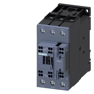
It is designed for DC load switching and auxiliary signal isolation in control panels where a compact, screwless termination is preferred. Rated DC-13 switching capacity: 10 A at 24 V, 2 A at 48 V and 60 V, 1 A at 110 V, 0.9 A at 125 V, 0.3 A at 220 V, 3 A at 400 V, and 0.6 A at 440 V. These are the contact ratings for breaking DC inductive loads — the voltage step matters because DC arcs sustain longer than AC, so the contactor's gap and arc-chamber design govern the curve. Mechanical switching frequency varies by duty class: 1 000 cycles/hour at AC-1 (resistive), 600 at AC-2 (slip-ring motor), 800 at AC-3 and AC-3e (squirrel-cage motor starting), and 250 at AC-4 (plugging/inching). The AC-4 ceiling is the binding limit for reversing or jogging applications. Coil inrush peaks at 2.6 A; the DC-13 switching times show an arcing period of 10–20 ms and a total DC operating time of 30–55 ms.
Panel Fit and Clearance
Footprint: 55 mm wide, 114 mm high, 130 mm deep. These are minimum air gaps for arc extinction and heat dissipation; stacking contactors closer than these values forces a derating review. Spring-type terminals accept 2× (0.5–2.5 mm²) solid or stranded conductors. The spring cage eliminates screw-torque variability on the coil circuit — one less thing to check during panel commissioning.
The storage ceiling exceeds the operating limit — that governs handling and transit, not running conditions. For panels in non-conditioned enclosures, the –25 °C floor is the cold-start boundary to verify.