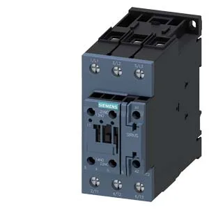
It mounts via screw and snap-on onto 35 mm DIN rail per DIN EN 60715, with the mounting position allowing +/-180° rotation on a vertical surface and +/-22.5° forward/backward tilt — useful when the panel layout forces an unconventional orientation. The coil is rated 20-33 V (AC/DC), with an inrush current peak of 3 A and steady-state draw of 2 VA at both 50 and 60 Hz. That 2 VA figure matters for transformer sizing on the control circuit — a multi-contactor panel needs the summed VA, not just the sealed power.
Duty-cycle and switching frequency
Maximum switching frequency depends on the utilisation category: 700 operations/hour for AC-1 (resistive), 500/h for AC-3 and AC-3e (standard motor starting), 350/h for AC-2 (slip-ring motor), and 150/h for AC-4 (plugging/inching). The AC-3e rating at 500/h is the one to use for a standard squirrel-cage motor start/stop cycle — it matches the AC-3 figure, so no derating for that variant. Arcing time runs 10-20 ms; the make and break times at both AC and DC are 30-55 ms. These are typical for a contactor of this frame size and inform the coordination with upstream short-circuit protection.
Auxiliary contact ratings and wiring
The contactor ships with an auxiliary switch block (18-1 configuration for main contacts). The auxiliary contacts are rated: 10 A at 24 V, 2 A at 48 V and 60 V, 1 A at 110 V, 0.9 A at 125 V, and 0.3 A at 220 V. These are the maximum continuous currents — useful for direct PLC input sensing or pilot-duty relay coils without an interposing relay. Main coil terminals are screw-type, accepting 2x (0.5-1.5 mm²) or 2x (0.75-2.5 mm²) solid or stranded wire. The auxiliary terminals share the same range. Strip length and ferrule sizing follow standard practice for this terminal class.
Environmental limits and clearances
Minimum clearances to adjacent components: 10 mm upwards, downwards, and forwards; 6 mm at the sides. In a dense DIN-rail layout, the 6 mm side gap is the binding constraint — plan the gland plate and wireway accordingly.