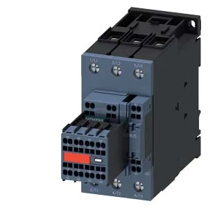
The Siemens SIRIUS 3RT2038-3CL24-3MA0 is a Size S2 power contactor rated for 65 A at 480 V and 15 hp at 230 V, built for switching motor loads in industrial control panels. Its spring-type terminals on the magnet coil and screw/snap-on mounting onto 35 mm DIN rail per DIN EN 60715 mean it lands in a standard panel footprint without special tooling — the 55 mm width and 114 mm height fit a typical 8-module wide enclosure row, provided the 178 mm depth is accounted for in gland-plate planning.
Duty-cycle limits and thermal reality
The contactor is rated for AC-3e maximum switching frequency of 500 1/h and AC-4 maximum at 150 1/h — the AC-4 figure governs plugging or inching duty where the motor is reversed or jogged under load. At AC-1 resistive loads it can cycle up to 700 1/h, but the thermal limit for the coil and main contacts is set by the operating ambient range of -25 to +60 °C, with storage tolerance from -55 to +80 °C. The mechanical endurance of 10 million typical cycles holds the unit on the grid for years in a pump or fan application, provided the electrical load does not exceed the rated making and breaking capacity at the selected duty class.
Auxiliary contact capacity and wiring
The main contact configuration is 18 normally open and 1 normally closed (18...1), and the auxiliary switch is listed as absent — meaning the contactor carries no factory-fitted auxiliary block. The auxiliary contact ratings at 24 V rated value is 6 A, at 48 V rated value 2 A, at 110 V rated value 1 A, and at 230 V rated value 0.3 A. The wire size accepted is 2x (0.5 to 2.5 mm²) solid or stranded, which is standard for control wiring in a 600 V class panel. The spring-type terminals on the coil eliminate the need for screwdriver torque checks during commissioning, provided the strip length is held to the manufacturer's specification.