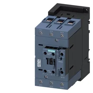
SIRIUS S3 power contactor — panel integration notes
It mounts via screw and snap-on onto 35 mm DIN rail per DIN EN 60715, and the mounting position allows +/-180° rotation on a vertical surface plus +/-22.5° forward/backward tilt — useful when fitting into tight or angled enclosures. The envelope is 70 mm wide, 140 mm high, 152 mm deep, so it occupies a standard S3 footprint on the rail.
Duty-cycle and switching frequency
Maximum switching rates are duty-class specific: 900 cycles/hour under AC-1 (resistive), 400/h under AC-2, 1000/h under AC-3 or AC-3e (standard motor starting), and 300/h under AC-4 (plugging/inching).
Conductor termination and auxiliary contact ratings
Main power terminals accept solid conductors from 2.5 to 16 mm² and stranded from 6 to 70 mm² — the stranded range is notably wider, so fine-stranded cable is preferred for full current capacity. Auxiliary/control terminals accept two conductors per clamp: 2x (0.5 to 1.5 mm²) solid or stranded, or 2x (0.75 to 2.5 mm²). The auxiliary switch is present (rated 10 A at 24 V, 2 A at 48/60 V, 1 A at 110 V, 0.9 A at 125 V, 0.3 A at 220 V, 3 A at 400 V, 0.8 A at 440 V) — these are the switching capacities for the built-in auxiliary contacts across common control voltages.