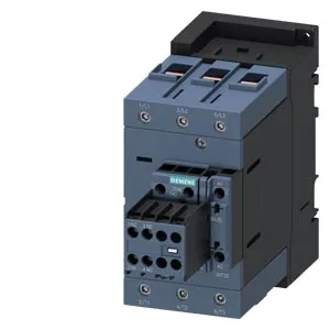
Mounting is via screw fixing or snap-on onto 35 mm DIN rail per EN 60715, with ±180° rotation on vertical surfaces and ±22.5° tilt forward/backward — useful when panel layout forces an unconventional orientation.
Switching Duty and Frequency — What the Ratings Mean
The contactor's maximum switching frequency varies by duty class: 1 000 operations per hour in AC-3 (squirrel-cage motor starting/running), 900 in AC-1 (resistive loads), 400 in AC-2 (slip-ring motor), and 300 in AC-4 (plugging/inching). The AC-3e rating also caps at 1 000 ops/h. These figures define the thermal cycling limit of the contactor — exceeding them accelerates contact wear, especially under AC-4 duty. Auxiliary contact ratings are voltage-dependent: 6 A at 24 V, 2 A at 48/60 V, 1 A at 110 V, 0.9 A at 125 V, 0.3 A at 220 V, and 3 A at 400 V. The 15 hp rating at 230 V confirms suitability for motor control at that voltage level. Arcing time spans 10 to 20 ms, with a make time of 10 to 21 ms at AC. These are the contactor's inherent switching times — useful for coordination with upstream protection devices.
Main circuit terminals accept solid conductors from 2.5 to 16 mm² and stranded from 6 to 70 mm². Auxiliary terminals take 2x (0.5 to 1.5 mm²) solid or 2x (0.75 to 2.5 mm²) stranded. The screw-type design is standard for panel wiring — no special tooling required beyond a screwdriver. These are the minimum air gaps to maintain for proper ventilation and arc containment.