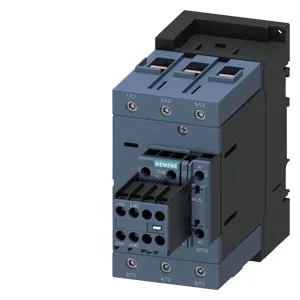
The envelope is 70 mm wide, 140 mm high, and 195 mm deep — the depth matters when spacing components in a shallow enclosure; the listed 195 mm is the body depth, not including coil terminals. Main power circuit wiring accepts solid conductors from 2.5 to 16 mm² and stranded conductors from 6 to 70 mm². Auxiliary and coil terminals accept two conductors per clamp: 2x 0.5–1.5 mm² solid or stranded, or 2x 0.75–2.5 mm². That range covers most panel-building practice without needing adapter lugs.
Switching duty and thermal limits
This contactor is rated for different switching frequencies depending on the utilization category. In AC-3 duty (squirrel-cage motor starting, switching off running motors) it manages up to 1,000 operating cycles per hour. AC-4 (plugging, inching) drops to 300 cycles/h. AC-1 (resistive loads) is 900 cycles/h, and AC-2 (slip-ring motors) is 400 cycles/h. The AC-3e rating also shows 1,000 cycles/h. These numbers define the thermal cycling the contactor can sustain — exceeding them shortens contact life. Power dissipation at 50 Hz is 0.35 W and at 60 Hz is 0.41 W — negligible for panel heat calculations but useful when sizing a control transformer for the coil circuit. Operating time (closing) is 10–21 ms; arcing time is 10–20 ms. Side clearance is 10 mm; upward and downward clearance is also 10 mm; forward clearance is 20 mm.
The built-in auxiliary switch is rated by voltage for DC switching: 6 A at 24 V, 2 A at 48 V and 60 V, 1 A at 110 V, 0.9 A at 125 V, 0.3 A at 220 V, and 0.8 A at 440 V. At 230 V AC the rating is 15 hp. At 400 V AC it is 3 A. These are the make/break capacities for the auxiliary contacts — useful when interlocking or signaling a PLC input.
The lifecycle stage for 3RT2045-1AL24 is current production. This is not a phase-out or NRND line.