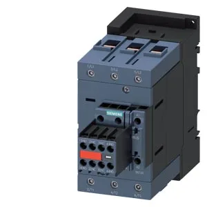
Dimensions: 70 mm wide, 140 mm high, 195 mm deep.
Wiring and conductor ranges
Main contact terminals accept solid conductors 2.5–16 mm² or stranded 6–70 mm². The magnet coil uses screw-type terminals. Auxiliary switch terminals accept 2x (0.5–1.5 mm²) solid or stranded, or 2x (0.75–2.5 mm²).
Switching performance and thermal limits
Rated for AC-3 duty at 1,000 operating cycles per hour maximum, AC-1 at 900/h, AC-2 at 400/h, AC-4 at 300/h. Arcing time is 10–20 ms at 50 Hz with a power factor of 0.38. Mechanical life typical 10,000,000 operations.
Built-in auxiliary switch rated: 6 A at 24 V, 2 A at 48/60 V, 1 A at 110 V, 0.9 A at 125 V, 0.3 A at 220 V, 3 A at 400 V, 0.8 A at 440 V. Main contact rating: 15 hp at 230 V.