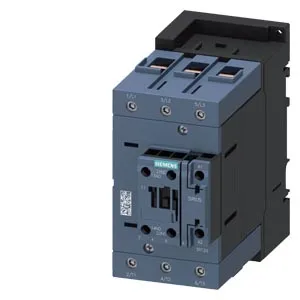
SIRIUS S3 frame, screw terminals, auxiliary switch onboard
The 3RT2046-1AN60 is a SIRIUS S3-frame power contactor from Siemens, rated for screw and snap-on mounting onto 35 mm standard mounting rail per DIN EN 60715. It comes with an auxiliary switch integrated, so you don't need a separate add-on block for basic feedback or interlocking. The main contacts are configured as 10 normally open and 2 normally closed, giving flexibility for motor starting or other load switching where a mix of N.O. and N.C. poles is needed. Mechanical endurance is rated at 10 million operating cycles typical, which aligns with the S3 frame's expected service life in moderate-duty applications like conveyor drives or pump panels.
Switching frequency and duty ratings
Maximum switching rates vary by duty class: 900 operations per hour in AC-1 (resistive), 850/h in AC-3 and AC-3e (standard motor starting), 350/h in AC-2 (slip-ring motor), and 250/h in AC-4 (plugging/inching). For most motor control panels, the AC-3 figure of 850/h is the one that governs the cycle time budget. The arcing time is specified at 10–20 ms for the main contacts, with a make time of 10–21 ms at AC. These numbers matter when coordinating with upstream short-circuit protection devices to ensure selective coordination. Power factor at rated load is 0.35 at 50 Hz and 0.41 at 60 Hz — this is the load-side power factor the contactor sees, not the coil power factor. It affects the real current drawn through the main poles.
Mounting, clearances, and environmental limits
Mounting position is flexible: ±180° rotation on a vertical surface, and can be tilted forward/backward by ±22.5° on a vertical surface. This simplifies panel layout when space is tight. Required clearances: 10 mm upwards, 20 mm forwards, 10 mm downwards, 10 mm at the side. These are the minimum air gaps to maintain for heat dissipation and arc flash containment. Operating temperature range is -25 to +60 °C, storage range is -55 to +80 °C. The -25 °C lower limit means it's suitable for unheated enclosures in most temperate climates, but not for deep-freeze applications without a heated cabinet.
Wiring and conductor sizes
Main circuit terminals accept solid conductors from 2.5 to 16 mm² and stranded conductors from 6 to 70 mm². The wide stranded range (up to 70 mm²) covers the full ampacity for the S3 frame's rated current without needing a terminal reducer. Auxiliary circuit terminals accept solid or stranded wire in sizes 2x (0.5–1.5 mm²) or 2x (0.75–2.5 mm²). The coil connection uses screw-type terminals, which are field-serviceable with a standard screwdriver.
Auxiliary contact ratings at various voltages
The auxiliary switch is rated for 10 A at 24 V, 2 A at 48 V and 60 V, 1 A at 110 V, 0.9 A at 125 V, 0.3 A at 220 V, 3 A at 400 V, and 0.8 A at 440 V. These are the thermal current ratings for the auxiliary contacts — important when feeding PLC inputs or pilot devices at different control voltages. At 230 V, the contactor is rated for 20 hp motor load, which is a standard NEMA motor rating. This gives a direct cross-reference for North American panel designs using horsepower-rated starters.
Lifecycle and sourcing
Sourced through authorized distribution channels. No stock-holding claim is made; this is a quoted-to-order line item.