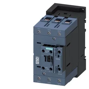
Siemens 3RT2046-1AP60-0UA0 — Contactors

Siemens 3RT2046-1AP60-0UA0 SIRIUS Power Contactor

MPN3RT2046-1AP60-0UA0
Active

Siemens SIRIUS 3RT2046-1AP60-0UA0 power contactor, S3 frame, screw-type coil terminals, auxiliary contacts, 152 mm depth, 70 mm width, 140 mm height, screw and snap-on mounting on 35 mm DIN rail.

StockContact for availability
Lead time3-5 Days wk
MOQ1 pcs
Sourced new & surplus through independent channelsAuthenticity-screened · ESD-safe packingListing updated Jul 2026
How we verify every order →

Specifications

Identification

3RT2046-1AP60-0UA0 — Identification
ParameterValue
Contactor frame sizeS3

Ratings & Performance

3RT2046-1AP60-0UA0 — Ratings & Performance
ParameterValue
Rated operational current, AC-12, max.10 A
Rated operational current, AC-4 @ 400 V80 A
Rated value @ 400 V3 A
Rated value @ 500 V2 A
Rated value @ 690 V1 A
Rated value @ 230 V6 A
Rated value @ 24 V10 A
Rated value @ 60 V2 A
Rated value @ 110 V1 A
Rated value @ 220 V0.3 A

Control & Coil

3RT2046-1AP60-0UA0 — Control & Coil
ParameterValue
Control supply voltage typeAC
Rated value @ 50 Hz0.36
Rated value @ 50 Hz220 V

Contacts & Poles

3RT2046-1AP60-0UA0 — Contacts & Poles
ParameterValue
Main poles3
Main NO contacts3
Auxiliary contact reliability1 faulty switching per 100 million (17 V, 1 mA)

Protection & Coordination

3RT2046-1AP60-0UA0 — Protection & Coordination
ParameterValue
Short-circuit coordination type 1, fusegG: 250 A (690 V, 100 kA), aM: 160 A (690 V, 100 kA), BS88: 200 A (415 V, 80 kA)
Short-circuit coordination type 2, fusegG: 160 A (690 V, 100 kA), aM: 100 A (690 V, 100 kA), BS88: 125 A (415 V, 80 kA)
Aux. switch short-circuit protection, fusegG: 10 A (500 V, 1 kA)

Connection & Mounting

3RT2046-1AP60-0UA0 — Connection & Mounting
ParameterValue
Main circuit connectionscrew-type terminals
Aux. / control circuit connectionscrew-type terminals
Conductor cross-section, solid2.5 ... 16 mm²
Conductor cross-section, solid or stranded2x (0.5 ... 1.5 mm²), 2x (0.75 ... 2.5 mm²)
Conductor cross-section, finely stranded w/ ferrule2x (0.5 ... 1.5 mm²), 2x (0.75 ... 2.5 mm²)
Mounting methodscrew and snap-on mounting onto 35 mm standard mounting rail according to DIN EN 60715
Side-by-side mountingYes

Durability

3RT2046-1AP60-0UA0 — Durability
ParameterValue
Durability (operating cycles, typ.)10 000 000
Durability with aux. switch block (cycles, typ.)10 000 000

Environmental

3RT2046-1AP60-0UA0 — Environmental
ParameterValue
Operating temperature range-25 ... +60 °C
Storage temperature range-55 ... +80 °C
Installation altitude, max.2 000 m

Mechanical

3RT2046-1AP60-0UA0 — Mechanical
ParameterValue
Width70 mm
Height140 mm
Depth152 mm

Specifications

3RT2046-1AP60-0UA0 — Specifications
ParameterValue
At AC10 ... 21 ms

Product details

152 mm depth — the panel clearance number

The 3RT2046-1AP60-0UA0: The 152 mm depth is the dimension that decides whether this S3-frame contactor fits your existing enclosure depth. On a 200 mm deep panel you have 48 mm behind the rail for wiring and arc chute clearance — tight but workable with the 10 mm upwards and 20 mm forward spacing requirements. Mounting is screw-and-snap-on onto 35 mm DIN rail per DIN EN 60715. The mounting position allows +/-180° rotation on a vertical surface and +/-22.5° tilt forward/backward — useful when the panel layout forces an odd angle.

Wire sizing and switching frequency limits

Solid wire range 2.5–16 mm² and stranded 6–70 mm² cover most motor feeder sizes from 4 mm² up to 50 mm². The screw-type coil terminals accept 2x (0.5–1.5 mm²) or 2x (0.75–2.5 mm²) — standard for control wiring. Switching frequency limits per duty class: AC-1 (resistive) 900 ops/h, AC-3 (motor start/run) 850 ops/h, AC-4 (jogging/inching) 250 ops/h. The AC-4 figure is the one that governs high-cycle reversing or plugging applications — if your line cycles more than 250 times per hour under AC-4, this contactor will overheat.

Auxiliary contact ratings — what they switch

The auxiliary switch is rated for 10 A at 24 V, 6 A at 230 V, and 3 A at 400 V. These are the control-circuit switching capacities — not the main pole ratings. If you're feeding a PLC input at 24 V, 10 A gives plenty of headroom for multiple loads. Arcing time is 10–20 ms, and the mechanical switching time at AC is 10–21 ms. That puts the total break time under 40 ms — fast enough for most safety circuits but verify coordination with your upstream breaker's trip curve.

Lifecycle and sourcing — active production

Lifecycle stage is listed as 'current' — Siemens still manufactures this part. For MRO spares, this is the direct drop-in for any panel built around the SIRIUS S3 frame. Operating temperature range -25 to +60 °C, storage -55 to +80 °C. The 10 mm side clearance and 10 mm downward clearance are the minimum air gaps for heat dissipation — don't crowd it against the panel wall.

Frequently asked questions

What is the switching frequency for jogging (AC-4) applications?

The maximum switching frequency under AC-4 duty is 250 operations per hour. For AC-3 motor starting it is 850 ops/h. If your application cycles faster than 250 ops/h under AC-4, you need a larger frame or a different contactor.

What wire sizes does the main circuit accept?

Solid conductors from 2.5 to 16 mm² and stranded conductors from 6 to 70 mm². The screw-type coil terminals accept 2x (0.5–1.5 mm²) or 2x (0.75–2.5 mm²).

MPN
3RT2046-1AP60-0UA0