Frame size and panel fit
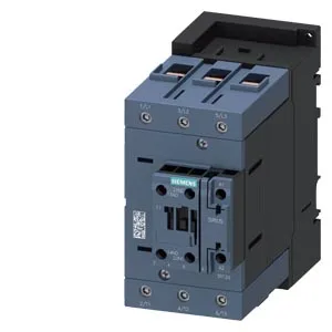
The 3RT2046-1AV00: The S3 frame measures 70 mm wide by 140 mm tall by 152 mm deep — that depth is the dimension that catches panel builders who assume a standard S2 envelope. The 152 mm depth means the contactor body extends farther behind the DIN rail than the smaller S2 siblings; verify the enclosure depth plus wiring channel clearance before committing the backpanel layout. Mounting is via screw or snap-on onto 35 mm standard mounting rail per DIN EN 60715. The mounting position allows ±180° rotation on a vertical surface and ±22.5° tilt forward or backward, which gives flexibility in tight retrofit panels provided the arc chute orientation stays within the manufacturer's allowed plane.
AC-3 motor switching at 480 V
The headline motor-switching figure is 96 A at 480 V in AC-3 duty — that is the current the contactor can make and break across the motor inrush and running cycle. For a 480 V three-phase motor, that rating typically covers a 75 hp (55 kW) induction motor; the 230 V rating of 20 hp confirms the same contactor derates linearly with voltage. Mechanical endurance is 10 million operating cycles typical, which is the figure for the contactor's life before the main contacts need inspection. The maximum switching rates vary by duty: 900 cycles/hour at AC-1 (resistive), 850 at AC-3 (motor running), and 250 at AC-4 (plugging/inching). For a conveyor or pump application cycling at AC-3, the 850 c/h ceiling is well above typical process rates, so the limiting factor is the coil duty cycle, not the contactor.
Termination and conductor range
Main power terminals accept solid conductors from 2.5 mm² up to 16 mm² and stranded conductors from 6 mm² up to 70 mm². That dual range means the same contactor lands both the incoming feeder (typically 50–70 mm² stranded for a 96 A circuit) and the smaller motor leads (down to 2.5 mm² solid) without needing adapter lugs — provided the terminal screw torque is set for the actual wire size. Auxiliary switch contacts are present, and the coil connection uses screw-type terminals. The auxiliary contact ratings at various control voltages are listed: 10 A at 24 V, 2 A at 48 V, 1 A at 110 V, 0.3 A at 230 V (–). These are the break capacities for the control circuit — a 24 VDC PLC output driving the coil through these aux contacts must stay within the 10 A limit, which is generous for a typical 24 VDC pilot duty load.
Clearance and ambient limits
Minimum air clearances around the contactor: 10 mm upwards, 10 mm downwards, 20 mm forwards, and 10 mm at the side. These are the free-space requirements for arc extinction and heat dissipation — stacking contactors closer than 10 mm side-to-side without a derating calculation risks thermal nuisance trips in a 60 °C ambient. Operating ambient temperature range is -25 °C to +60 °C; storage range is -55 °C to +80 °C. The 60 °C ceiling is typical for industrial enclosures without active cooling; if the panel ambient exceeds 60 °C, the contactor must be derated per the Siemens SIRIUS application manual — the evidence does not give a derating curve, so that calculation is the panel designer's responsibility.