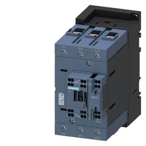
Siemens 3RT2046-3AR60 — Contactors

Siemens 3RT2046-3AR60 SIRIUS Power Contactor, S3, 20 hp at 4

MPN3RT2046-3AR60
Active

Siemens SIRIUS power contactor, 3RT2046-3AR60, size S3, screw and snap-on mounting onto 35 mm DIN rail, spring-type coil terminals, 20 hp at 400 V.

Source DocumentedChannel stated on listing & quote
Condition PhotosReal unit photos / video on request
WhatsApp AnswersFast human replies for machine-down parts
Worldwide DispatchDHL/FedEx — transit quoted per order
Independent China distributor & sourcing agent· Listing updated Sep 2026

Specifications

3RT2046-3AR60 — Identification
ParameterValue
Contactor frame sizeS3
3RT2046-3AR60 — Ratings & Performance
ParameterValue
Rated operational current, AC-12, max.10 A
Rated operational current, AC-4 @ 400 V80 A
Rated value @ 400 V3 A
Rated value @ 500 V2 A
Rated value @ 690 V1 A
Rated value @ 230 V20 hp
Rated value @ 24 V10 A
Rated value @ 60 V2 A
Rated value @ 110 V1 A
Rated value @ 220 V0.3 A
3RT2046-3AR60 — Control & Coil
ParameterValue
Control supply voltage typeAC
Rated value @ 50 Hz0.35
Rated value @ 50 Hz400 V
3RT2046-3AR60 — Contacts & Poles
ParameterValue
Main poles3
Main NO contacts3
Auxiliary contact reliability1 faulty switching per 100 million (17 V, 1 mA)
3RT2046-3AR60 — Protection & Coordination
ParameterValue
Short-circuit coordination type 1, fusegG: 250 A (690 V, 100 kA), aM: 160 A (690 V, 100 kA), BS88: 200 A (415 V, 80 kA)
Short-circuit coordination type 2, fusegG: 160 A (690 V, 100 kA), aM: 100 A (690 V, 100 kA), BS88: 125 A (415 V, 80 kA)
Aux. switch short-circuit protection, fusegG: 10 A (500 V, 1 kA)
3RT2046-3AR60 — Connection & Mounting
ParameterValue
Main circuit connectionscrew-type terminals
Aux. / control circuit connectionspring-loaded terminals
Conductor cross-section, solid2.5 ... 16 mm²
Conductor cross-section, solid or stranded2x (0.5 ... 2.5 mm²)
Conductor cross-section, finely stranded w/ ferrule2x (0.5 ... 1.5 mm²)
Mounting methodscrew and snap-on mounting onto 35 mm DIN rail according to DIN EN 60715
Side-by-side mountingYes
3RT2046-3AR60 — Durability
ParameterValue
Durability (operating cycles, typ.)10 000 000
Durability with aux. switch block (cycles, typ.)10 000 000
3RT2046-3AR60 — Environmental
ParameterValue
Operating temperature range-25 ... +60 °C
Storage temperature range-55 ... +80 °C
Installation altitude, max.2 000 m
3RT2046-3AR60 — Mechanical
ParameterValue
Width70 mm
Height140 mm
Depth152 mm
3RT2046-3AR60 — Specifications
ParameterValue
At AC10 ... 21 ms

Product details

It mounts via screw or snap-on onto 35 mm DIN rail per DIN EN 60715, and its mounting position allows +/-180° rotation on a vertical surface plus +/-22.5° tilt forward/backward, giving panel builders flexibility in tight enclosures. The contactor carries a 20 hp rating at 400 V, which is the motor horsepower figure that governs its selection for three-phase induction motor duty. It is rated for AC-3 switching at up to 850 operating cycles per hour, matching the duty cycle of conveyors, pumps, and compressors.

The 20 hp at 400 V rating is the headline motor-switching capacity — this contactor is sized for a 20 hp, 400 V three-phase induction motor in AC-3 duty (starting and stopping under load). The AC-3 switching frequency of 850 cycles/hour means it can handle frequent starts typical of a conveyor or compressor without overheating. For resistive loads (AC-1), the contactor is rated at 900 cycles/hour. For plugging or inching duty (AC-4), the rate drops to 250 cycles/hour — a real constraint if the application involves reversing or jogging. The auxiliary contact block is present and carries its own voltage-dependent current ratings: 10 A at 24 V, 2 A at 48 V, 2 A at 60 V, 1 A at 110 V, 0.9 A at 125 V, 0.3 A at 220 V, 3 A at 400 V, and 0.8 A at 440 V (-). These are the maximum currents the auxiliary contacts can break at those voltages — important for control circuit design. The contactor is rated for 50/60 Hz operation with a power factor of 0.35 at 50 Hz and 0.41 at 60 Hz — these are the load power factors the contactor is designed to switch, not the coil draw.

Wiring and Panel Integration

The main power terminals accept solid conductors from 2.5 to 16 mm² and stranded conductors from 6 to 70 mm². The coil terminals are spring-type, accepting 2x (0.5 to 2.5 mm²) solid or stranded. This is a mixed termination scheme — spring-cage for the coil, screw-type for the main poles — so the wireman needs both a screwdriver and a spring-release tool. Physical dimensions: 70 mm wide, 140 mm high, 152 mm deep. These clearances are for arc flash and heat dissipation — not just mechanical fit. The contactor has 10 main contacts and an arcing time of 10 to 20 ms, with a switching time at AC of 10 to 21 ms.

Because it is active and widely used, there is no pressure to find a substitute. The closest functional peer in the SIRIUS family would be a different frame size or coil voltage variant — but the 3RT2046-3AR60 is the specific S3, 20 hp at 400 V configuration. If you are sourcing for a panel that was specified around a smaller SIRIUS contactor like the 3RT2027-1AP60, the 3RT2046-3AR60 is a larger frame (S3 vs S0) and will not drop in without panel rework — different footprint, different terminal spacing.

Frequently asked questions

Will the 3RT2046-3AR60 drop into a panel designed for a 3RT2027-1AP60?

No. The 3RT2046-3AR60 is size S3, while the 3RT2027-1AP60 is a smaller frame size (S0). The physical dimensions differ — the S3 is 70 mm wide, 140 mm high, 152 mm deep — so it will not fit the same DIN rail footprint or terminal layout without panel rework.

MPN
3RT2046-3AR60