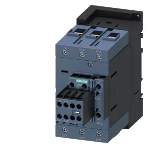
Siemens 3RT2047-1NF34 — Contactors

Siemens 3RT2047-1NF34 Power Contactor, SIRIUS, Coil 83-155 V

MPN3RT2047-1NF34
Active

Siemens SIRIUS power contactor, order code 3RT2047-1NF34, Size S3, coil voltage 83-155 V, screw-type terminals, auxiliary switch included, screw and snap-on mounting on 35 mm DIN rail.

Sourced new & surplus through independent channelsAuthenticity-screened · ESD-safe packingListing updated Aug 2026

Specifications

3RT2047-1NF34 — Identification
ParameterValue
Contactor frame sizeS3
3RT2047-1NF34 — Ratings & Performance
ParameterValue
Rated operational current, AC-12, max.10 A
Rated operational current, AC-4 @ 400 V97 A
Rated value @ 400 V3 A
Rated value @ 500 V2 A
Rated value @ 690 V1 A
Rated value @ 230 V20 hp
Rated value @ 24 V6 A
Rated value @ 60 V2 A
Rated value @ 110 V1 A
Rated value @ 220 V0.3 A
3RT2047-1NF34 — Control & Coil
ParameterValue
Control supply voltage typeAC/DC
Rated value @ 50 Hz3.5 VA
Rated value @ 50 Hz83 ... 155 V
3RT2047-1NF34 — Contacts & Poles
ParameterValue
Main poles3
Main NO contacts3
Auxiliary contact reliability1 faulty switching per 100 million (17 V, 1 mA)
3RT2047-1NF34 — Protection & Coordination
ParameterValue
Short-circuit coordination type 1, fusegG: 250 A (690 V, 100 kA), aM: 160 A (690 V, 100 kA), BS88: 200 A (415 V, 80 kA)
Short-circuit coordination type 2, fusegG: 200A (690V,100kA), aM: 100A (690V,100kA), BS88: 160A (415V,80kA)
Aux. switch short-circuit protection, fusegG: 10 A (500 V, 1 kA)
3RT2047-1NF34 — Connection & Mounting
ParameterValue
Main circuit connectionscrew-type terminals
Aux. / control circuit connectionscrew-type terminals
Conductor cross-section, solid2.5 ... 16 mm²
Conductor cross-section, solid or stranded2x (0.5 ... 1.5 mm²), 2x (0.75 ... 2.5 mm²)
Conductor cross-section, finely stranded w/ ferrule2x (0.5 ... 1.5 mm²), 2x (0.75 ... 2.5 mm²)
Mounting methodscrew and snap-on mounting onto 35 mm DIN rail according to DIN EN 60715
Side-by-side mountingYes
3RT2047-1NF34 — Durability
ParameterValue
Durability (operating cycles, typ.)10 000 000
Durability with aux. switch block (cycles, typ.)10 000 000
3RT2047-1NF34 — Environmental
ParameterValue
Operating temperature range-25 ... +60 °C
Storage temperature range-55 ... +80 °C
Installation altitude, max.2 000 m
3RT2047-1NF34 — Mechanical
ParameterValue
Width70 mm
Height140 mm
Depth195 mm
3RT2047-1NF34 — Specifications
ParameterValue
At AC38 ... 57 ms

Product details

What the coil voltage rating means for fit

That range covers common 110-120 VAC control circuits and 110 VDC applications — you can land it on a standard 110 V control transformer without worrying about undervoltage dropout. The inrush peak is 1.5 A, so your control transformer and fuse need to handle that transient without sagging below the 83 V dropout threshold.

Mechanical and wiring fit

This is a Size S3 contactor — 70 mm wide, 140 mm high, 195 mm deep. The main power terminals accept solid wire 2.5 to 16 mm² or stranded 6 to 70 mm² — that's a broad range, so you can land 6 AWG or 1/0 cable without adapters. Auxiliary control wiring uses dual wire entries: 2x (0.5-1.5 mm²) or 2x (0.75-2.5 mm²). Clearance to grounded parts: 10 mm upward and downward, 20 mm forward, 10 mm at the side. If you're packing multiple contactors on a DIN rail, those gaps are the minimum for arc flash and heat dissipation — don't crowd them tighter.

Switching performance and auxiliary contacts

The main contacts are rated for 10 to 2 A, and the contactor carries an auxiliary switch as standard — no separate add-on block needed for basic status feedback. Maximum switching frequency depends on load: 900 cycles/hour at AC-1 (resistive), 850 at AC-3 (motor start/run), 350 at AC-2 (slip-ring motor), and 200 at AC-4 (plugging/reversing). For a conveyor motor running AC-3 duty, that's one start every ~4 seconds — fine for normal cycling, but not for high-speed jogging.

Frequently asked questions

What are the auxiliary contact configurations on the 3RT2047-1NF34?

The contactor includes an auxiliary switch as standard — no separate add-on block required for basic status feedback. Auxiliary wiring accepts dual conductors: 2x (0.5-1.5 mm²) or 2x (0.75-2.5 mm²).

What is 3RT2047-1NF34's listed depth (195 mm) on this component line?

The depth is 195 mm. Overall dimensions: 70 mm wide, 140 mm high, 195 mm deep. Clearance to grounded parts: 10 mm upward/downward, 20 mm forward, 10 mm at the side.

What is 3RT2047-1NF34's listed solid (2.5... 16 mm²) on this component line?

The solid wire range is 2.5 to 16 mm². Stranded wire range is 6 to 70 mm². Auxiliary terminals accept 2x (0.5-1.5 mm²) or 2x (0.75-2.5 mm²).

Where can I buy 3RT2047-1NF34?

This part is sourced to order. Contact us for current pricing and availability at quote time.

MPN
3RT2047-1NF34