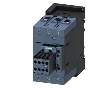
Part identity and deployment context
It mounts via screw and snap-on onto 35 mm DIN rail per DIN EN 60715, with a mounting position that allows +/-180° rotation on a vertical surface and +/-22.5° tilt forward/backward, giving panel builders flexibility in tight enclosures. Its coil draws 3.5 VA at both 50 Hz and 60 Hz, with an inrush current peak of 65 A — a figure to note when sizing control transformers, especially if multiple contactors pull in simultaneously.
The coil operates on a rated value of 175-280 V AC. The screw-type terminals for the magnet coil accept solid conductors from 2.5 to 16 mm² and stranded from 6 to 70 mm², with auxiliary contact wiring accepting 2x (0.5-1.5 mm²) solid or stranded and 2x (0.75-2.5 mm²). Switching frequency ratings tell you the thermal limit of the contactor under different load types: AC-1 (resistive) allows up to 900 cycles per hour, AC-3 (standard motor starting) 850 cycles/h, AC-2 (slip-ring motor) 350 cycles/h, and AC-4 (plugging/inching) 200 cycles/h. For a conveyor or pump running a normal start/stop cycle, the AC-3 rate of 850 cycles/h is ample; if your application involves frequent reversing or jogging, the AC-4 limit of 200 cycles/h governs the real duty cycle. For DC switching, the contactor carries breaking capacities of 6 A at 24 V rated value, 2 A at 48 V, 2 A at 60 V, and 1 A at 110 V. These are the maximum currents the main contacts can interrupt under DC inductive loads — DC arcs are harder to extinguish than AC, so these values are significantly lower than the AC motor ratings. If you need to switch a DC motor or solenoid bank, stay within these limits.
Dimensions and wiring clearances
The contactor measures 70 mm wide, 140 mm high, and 195 mm deep. That 195 mm depth includes the coil terminals and arc chamber — verify it fits your enclosure depth, especially if a duct cover or door-mounted device intrudes.