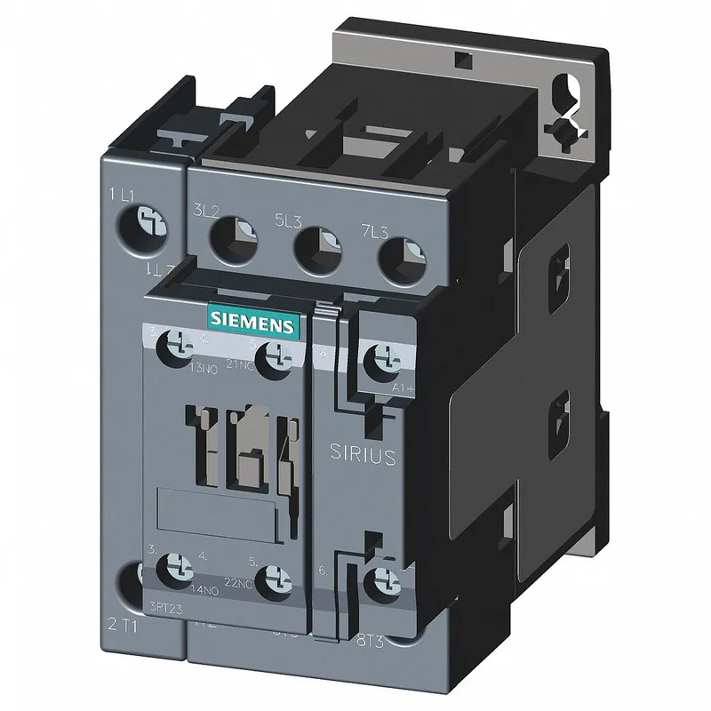
Siemens 3RT2325-1AK60 — Contactors

Siemens 3RT2325-1AK60 SIRIUS Contactor, Size S0

MPN3RT2325-1AK60
Active

Siemens SIRIUS 3RT2325-1AK60 contactor, size S0, screw-type coil terminals, AC coil voltage, 1 NO + 1 NC auxiliary contacts, screw and snap-on mounting on 35 mm DIN rail.

$34.29Ref. price · indicative, final on quote
Sourced new & surplus through independent channelsAuthenticity-screened · ESD-safe packingListing updated Aug 2026

Specifications

3RT2325-1AK60 — Identification
ParameterValue
Contactor frame sizeS0
3RT2325-1AK60 — Ratings & Performance
ParameterValue
Rated operational current, AC-12, max.10 A
Rated operational current, AC-4 @ 400 V7.5 kW
Rated value @ 400 V3 A
Rated value @ 500 V2 A
Rated value @ 690 V1 A
Rated value @ 230 V10 A
Rated value @ 24 V10 A
Rated value @ 60 V6 A
Rated value @ 110 V1 A
Rated value @ 220 V0.3 A
3RT2325-1AK60 — Control & Coil
ParameterValue
Control supply voltage typeAC
Rated value @ 50 Hz0.25
Rated value @ 50 Hz110 V
3RT2325-1AK60 — Contacts & Poles
ParameterValue
Main poles4
Main NO contacts4
Auxiliary contact reliability1 faulty switching per 100 million (17 V, 1 mA)
3RT2325-1AK60 — Protection & Coordination
ParameterValue
Short-circuit coordination type 1, fusegG: 63 A (690 V, 100 kA)
Short-circuit coordination type 2, fusegG: 20 A (690 V, 100 kA)
Aux. switch short-circuit protection, fusegG: 10 A (690 V, 1 kA)
3RT2325-1AK60 — Connection & Mounting
ParameterValue
Main circuit connectionscrew-type terminals
Aux. / control circuit connectionscrew-type terminals
Conductor cross-section, solid2x (0.5 ... 1.5 mm²), 2x (0.75 ... 2.5 mm²)
Conductor cross-section, solid or stranded2x (0.5 ... 1.5 mm²), 2x (0.75 ... 2.5 mm²)
Conductor cross-section, finely stranded w/ ferrule2x (0.5 ... 1.5 mm²), 2x (0.75 ... 2.5 mm²)
Mounting methodscrew and snap-on mounting onto 35 mm DIN rail according to DIN EN 60715
Side-by-side mountingYes
3RT2325-1AK60 — Durability
ParameterValue
Durability (operating cycles, typ.)10 000 000
Durability with aux. switch block (cycles, typ.)10 000 000
3RT2325-1AK60 — Environmental
ParameterValue
Operating temperature range-25 ... +60 °C
Storage temperature range-55 ... +80 °C
Installation altitude, max.2 000 m
3RT2325-1AK60 — Mechanical
ParameterValue
Width60 mm
Height85 mm
Depth97 mm
3RT2325-1AK60 — Specifications
ParameterValue
At AC4 ... 16 ms

Product details

Lifecycle and Sourcing Reality

The 3RT2325-1AK60: As a current-production SIRIUS contactor, it supports full part genealogy and traceability requirements for automotive Tier-1 PPAP submissions — the manufacturer maintains lot-level records.

Auxiliary Contact Ratings: What They Mean for Your Control Circuit

The built-in 1 NO + 1 NC auxiliary switch is rated for AC-15 and DC-13 loads across a wide voltage range: 10 A at 24 V AC, 10 A at 230 V AC, and 3 A at 400 V AC for the NO contact; the NC contact carries 6 A at 60 V DC, 2 A at 500 V DC, and 0.1 A at 600 V DC. These ratings cover typical PLC digital inputs, relay coils, and indicator lamps. The 10 A at 230 V AC rating means this auxiliary can directly switch a moderate-sized contactor coil or a bank of solenoid valves without an interposing relay. The DC-13 ratings (inductive DC loads) are the limiting factor for DC control circuits: 6 A at 60 V DC drops to 0.3 A at 220 V DC. For 24 V DC control, the 10 A rating applies — adequate for most PLC output modules.

Mechanical and Environmental Fit

The S0 frame size measures 97 mm deep by 60 mm wide by 85 mm high — a compact footprint that fits standard 35 mm DIN rail per DIN EN 60715. The screw-and-snap-on mounting allows tool-free installation and removal for panel servicing. Operating temperature range is -25 to +60 °C, with storage from -55 to +80 °C. This covers most indoor industrial environments including unheated warehouses and panel interiors near machinery. Mounting position is flexible: ±180° rotation on a vertical surface, plus ±22.5° forward/backward tilt. This accommodates tight enclosures or angled sub-panels without derating.

Wiring and Termination Details

Main contact wiring accepts stranded conductors from 1 to 10 mm². Auxiliary and coil terminals accept solid wire in two sizes: 2x (0.5 to 1.5 mm²) or 2x (0.75 to 2.5 mm²). The coil uses screw-type terminals (not cage clamps) — ensure a proper torque driver is available during panel assembly. The AC coil draws 0.25 VA at 50 Hz and 0.28 VA at 60 Hz, negligible for most control transformers. Clearance distances: 10 mm upwards and forwards, 10 mm downwards, 6 mm at the sides. These are the minimum air gaps to adjacent metalwork or other devices for proper heat dissipation and arc clearance.

Mechanical Endurance and Switching Performance

Mechanical endurance is rated at 10 million operations typical — this is the expected life before mechanical wear (spring fatigue, pivot wear) rather than electrical contact erosion. In a cycling application at 1 operation per second, that is over 115 days of continuous duty. Arcing time is 10 ms (fixed), with a make time of 4 to 16 ms and break time of 4 to 16 ms at AC. These switching times are consistent across the operating range and are compatible with standard PLC scan cycles.

Frequently asked questions

What is the auxiliary contact configuration on the 3RT2325-1AK60?

It has one normally open (NO) and one normally closed (NC) auxiliary contact built in. The NO contact is rated 10 A at 230 V AC; the NC contact is rated 6 A at 60 V DC. This covers most PLC input and relay coil switching needs without an add-on block.

What wire sizes does the 3RT2325-1AK60 accept?

Main contacts accept stranded wire from 1 to 10 mm². Auxiliary and coil terminals accept solid wire: 2x (0.5 to 1.5 mm²) or 2x (0.75 to 2.5 mm²). All terminals are screw-type.

What are the mounting clearances required for the 3RT2325-1AK60?

Minimum air gaps: 10 mm upwards, 10 mm forwards, 10 mm downwards, and 6 mm at the sides. These ensure adequate cooling and arc clearance when mounted on DIN rail.

MPN
3RT2325-1AK60