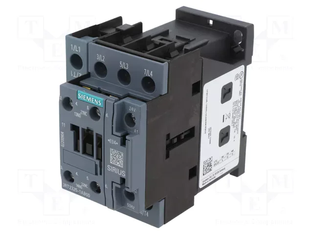
Siemens 3RT2325-1BG40 — Contactors

Siemens 3RT2325-1BG40 SIRIUS Contactor, S0 Frame, 24 VDC Coi

MPN3RT2325-1BG40
Active

Siemens SIRIUS contactor, size S0, 24 VDC screw-type coil, screw and snap-on DIN rail mount, 3RT2325-1BG40.

Source DocumentedChannel stated on listing & quote
Condition PhotosReal unit photos / video on request
WhatsApp AnswersFast human replies for machine-down parts
Worldwide DispatchDHL/FedEx — transit quoted per order
Independent China distributor & sourcing agent· Listing updated Sep 2026

Specifications

3RT2325-1BG40 — Identification
ParameterValue
Contactor frame sizeS0
3RT2325-1BG40 — Ratings & Performance
ParameterValue
Rated operational current, AC-12, max.10 A
Rated operational current, AC-4 @ 400 V7.5 kW
Rated value @ 400 V3 A
Rated value @ 500 V2 A
Rated value @ 690 V1 A
Rated value @ 230 V10 A
Rated value @ 24 V10 A
Rated value @ 60 V6 A
Rated value @ 110 V1 A
Rated value @ 220 V0.3 A
3RT2325-1BG40 — Control & Coil
ParameterValue
Control supply voltage typeDC
3RT2325-1BG40 — Contacts & Poles
ParameterValue
Main poles4
Main NO contacts4
Auxiliary contact reliability1 faulty switching per 100 million (17 V, 1 mA)
3RT2325-1BG40 — Protection & Coordination
ParameterValue
Short-circuit coordination type 1, fusegG: 63 A (690 V, 100 kA)
Short-circuit coordination type 2, fusegG: 20 A (690 V, 100 kA)
Aux. switch short-circuit protection, fusegG: 10 A (690 V, 1 kA)
3RT2325-1BG40 — Connection & Mounting
ParameterValue
Main circuit connectionscrew-type terminals
Aux. / control circuit connectionscrew-type terminals
Conductor cross-section, solid2x (0.5 ... 1.5 mm²), 2x (0.75 ... 2.5 mm²)
Conductor cross-section, solid or stranded2x (0.5 ... 1.5 mm²), 2x (0.75 ... 2.5 mm²)
Conductor cross-section, finely stranded w/ ferrule2x (0.5 ... 1.5 mm²), 2x (0.75 ... 2.5 mm²)
Mounting methodscrew and snap-on mounting onto 35 mm DIN rail according to DIN EN 60715
Side-by-side mountingYes
3RT2325-1BG40 — Durability
ParameterValue
Durability (operating cycles, typ.)10 000 000
Durability with aux. switch block (cycles, typ.)10 000 000
3RT2325-1BG40 — Environmental
ParameterValue
Operating temperature range-25 ... +60 °C
Storage temperature range-55 ... +80 °C
Installation altitude, max.2 000 m
3RT2325-1BG40 — Mechanical
ParameterValue
Width60 mm
Height85 mm
Depth107 mm

Product details

The auxiliary contact block delivers 10 A at 24 VDC, with a full DC-13 switching curve covering 2 A at 48 V, 6 A at 60 V, 1 A at 110 V, 0.9 A at 125 V, 0.3 A at 220 V, and 10 A at 230 V — so the same auxiliary set handles 24 V PLC signals and 230 V indicator loads without a separate relay.

The 60 mm wide, 85 mm tall, 107 mm deep footprint fits standard S0 contactor spacing. Side clearance of 6 mm to adjacent devices; 10 mm clearance upward, downward, and forward. Stranded main-circuit wiring accepts 1 to 10 mm²; auxiliary terminals take 2x (0.5 to 1.5 mm²) solid or 2x (0.75 to 2.5 mm²) stranded.

The arcing time on the main contacts is 10 to 10 ms, and the DC coil dropout timing is 15 to 18 ms.

The auxiliary switch is rated for DC switching across the voltage range, not just a single point. At 24 V it handles 10 A — enough for a bank of solenoid valves or indicator lamps. At 48 V the rating drops to 2 A, and at 125 V to 0.9 A. The 230 V rating is 10 A, but that is an AC value. For DC loads above 60 V, derate to the listed DC curve: 1 A at 110 V, 0.9 A at 125 V, 0.3 A at 220 V, 0.1 A at 600 V, and 1 A at 690 V. The full-scale value of 1.1 and initial value of 0.8 likely refer to the coil pickup and dropout multipliers — the coil holds at 80% of rated voltage and picks up at 110%.

Frequently asked questions

What is the depth of 3RT2325-1BG40?

The depth is 107 mm. Combined with a width of 60 mm and height of 85 mm, it fits standard S0 contactor spacing.

What wire sizes does the 3RT2325-1BG40 accept?

Main contacts accept stranded wire from 1 to 10 mm². Auxiliary terminals accept 2x (0.5 to 1.5 mm²) solid or 2x (0.75 to 2.5 mm²) stranded.

MPN
3RT2325-1BG40