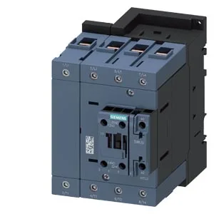
Siemens 3RT2344-1NB30 — Contactors

Siemens 3RT2344-1NB30 SIRIUS Contactor, Size S3, 20-33 V AC/

MPN3RT2344-1NB30
Active

Siemens SIRIUS contactor, size S3, 3RT2344-1NB30, 20-33 V AC/DC coil, main contacts 6-70 mm² stranded, screw and snap-on 35 mm DIN rail mounting.

Source DocumentedChannel stated on listing & quote
Condition PhotosReal unit photos / video on request
WhatsApp AnswersFast human replies for machine-down parts
Worldwide DispatchDHL/FedEx — transit quoted per order
Independent China distributor & sourcing agent· Listing updated Sep 2026

Specifications

3RT2344-1NB30 — Identification
ParameterValue
Contactor frame sizeS3
3RT2344-1NB30 — Ratings & Performance
ParameterValue
Rated operational current, AC-12, max.10 A
Rated value @ 400 V3 A
Rated value @ 500 V2 A
Rated value @ 690 V1 A
Rated value @ 230 V6 A
Rated value @ 24 V10 A
Rated value @ 60 V6 A
Rated value @ 110 V1 A
Rated value @ 220 V0.3 A
3RT2344-1NB30 — Control & Coil
ParameterValue
Control supply voltage typeAC/DC
Rated value @ 50 Hz3.5 VA
Rated value @ 50 Hz20 ... 33 V
3RT2344-1NB30 — Contacts & Poles
ParameterValue
Main poles4
Main NO contacts4
Auxiliary contact reliability1 faulty switching per 100 million (17 V, 1 mA)
3RT2344-1NB30 — Protection & Coordination
ParameterValue
Short-circuit coordination type 1, fusegG: 250 A (690 V, 100 kA)
Short-circuit coordination type 2, fusegR: 250 A (690 V, 100 kA)
Aux. switch short-circuit protection, fusegG: 10 A (690 V, 1 kA)
3RT2344-1NB30 — Connection & Mounting
ParameterValue
Main circuit connectionscrew-type terminals
Aux. / control circuit connectionscrew-type terminals
Conductor cross-section, solid2x (0.5 ... 1.5 mm²), 2x (0.75 ... 2.5 mm²)
Conductor cross-section, solid or stranded2x (0.5 ... 1.5 mm²), 2x (0.75 ... 2.5 mm²)
Conductor cross-section, finely stranded w/ ferrule2x (0.5 ... 1.5 mm²), 2x (0.75 ... 2.5 mm²)
Mounting methodscrew and snap-on mounting onto 35 mm DIN rail according to DIN EN 60715
Side-by-side mountingYes
3RT2344-1NB30 — Durability
ParameterValue
Durability (operating cycles, typ.)10 000 000
Durability with aux. switch block (cycles, typ.)10 000 000
3RT2344-1NB30 — Environmental
ParameterValue
Operating temperature range-25 ... +60 °C
Storage temperature range-55 ... +80 °C
Installation altitude, max.2 000 m
3RT2344-1NB30 — Mechanical
ParameterValue
Width96 mm
Height140 mm
Depth152 mm
3RT2344-1NB30 — Specifications
ParameterValue
At AC38 ... 57 ms

Product details

Mechanical endurance and switching cycles

The 3RT2344-1NB30: Mechanical endurance is rated at 10 million operations typical, and the main contact electrical endurance spans 10 to 2 million cycles depending on load current — the 10 million figure applies at light loads, 2 million at full rated current.

Auxiliary switch and contact ratings

An auxiliary switch is built in, with screw-type coil terminals. The auxiliary contacts are rated across a range of DC voltages: 10 A at 24 V, 6 A at 60 V, 2 A at 48 V, 1 A at 110 V, 0.9 A at 125 V, and 0.3 A at 220 V. At 230 V AC the rating is 6 A. These figures govern the pilot duty capability — a 24 VDC PLC output driving the auxiliary contact sees a 10 A make/break, which is generous for most signal-level loads but confirms the contact is rated for small solenoid valves or indicator lamps, not power switching.

The S3 frame dimensions are 140 mm height, 96 mm width, 152 mm depth. That depth is the critical dimension for shallow enclosures — 152 mm means the contactor body plus wiring space typically needs a 200 mm deep gland plate or deeper enclosure to avoid bending cables sharply.

Frequently asked questions

What is the coil voltage range and type?

The coil is rated 20-33 V AC/DC, with a typical inrush peak of 6.5 A and a holding power of 3.5 VA at both 50 and 60 Hz. The coil terminals are screw-type.

What wire sizes do the main contacts accept?

The main contact terminals accept stranded wire from 6 mm² up to 70 mm². The auxiliary and coil terminals accept solid or stranded 0.5 to 2.5 mm².

What are the mounting dimensions and clearances?

The S3 frame measures 140 mm high, 96 mm wide, 152 mm deep. Required clearances: 10 mm above, 10 mm below, 10 mm sides, 20 mm front. Mounts on 35 mm DIN rail per DIN EN 60715 with screw or snap-on fastening.

What is the mechanical and electrical endurance?

Mechanical endurance is 10 million operations typical. Electrical endurance for the main contacts ranges from 10 million cycles at light load down to 2 million cycles at full rated current.

MPN
3RT2344-1NB30