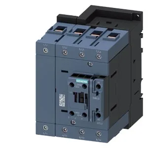
The coil pulls 3.5 VA at both 50 Hz and 60 Hz, with a 6.5 A inrush peak — that's a modest control-transformer load, so you can gang several on a single 24 VDC supply without oversizing it. The coil holds from 20 V up to 33 V (AC or DC), with a dropout threshold around 80% of rated (0.8 initial value) and a 1.1x full-scale overvoltage tolerance. That's a standard contactor response — fast enough for motor starting, not for a safety pulse. Main contact ratings are given as 10-2 (likely a thermal current / utilization category shorthand — check the full datasheet for AC-3 vs AC-1 values). The auxiliary switch is included and carries its own ratings: 10 A at 24 V, 6 A at 60 V, 2 A at 48 V, 1 A at 110 V, 0.9 A at 125 V, 0.3 A at 220 V, and 6 A at 230 V. That covers most control-voltage levels you'll see in a panel — 24 VDC, 120 VAC, 230 VAC — so the aux contacts can drive PLC inputs or pilot lights without an interposer relay.
Wiring and panel fit
Power wiring accepts stranded conductors from 6 to 70 mm² — that's a wide range, covering everything from a 4 mm² motor feed up to a 50 mm² bus. The coil and auxiliary terminals take solid wire 0.5-1.5 mm² or stranded 0.75-2.5 mm², with two conductors per terminal. That's the standard spring-cage or screw-clamp range for control wiring. Dimensions: 140 mm high, 96 mm wide, 152 mm deep. That's a size S3 footprint — roughly 4 inches wide, so it takes up one standard 96 mm DIN-rail slot. Two auxiliary contact blocks can be attached (attachable = 2), expanding the control interface without widening the footprint.