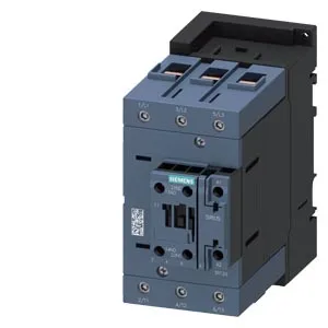
It uses an AC coil with screw-type terminals and includes an auxiliary switch. The contactor mounts via screw or snap-on onto 35 mm DIN rail per DIN EN 60715, and the mounting position allows +/-180° rotation on a vertical surface plus +/-22.5° tilt forward/backward — useful when panel layout forces an unconventional orientation. Rated for 10 A at 24 V, 6 A at 230 V, and 3 A at 400 V across its auxiliary contacts, with a mechanical life of 10,000,000 cycles typical. The AC coil draws a power factor of 0.36 at 50 Hz and 0.4 at 60 Hz. Wire termination accepts solid conductors: 2x (0.5 to 1.5 mm²) and 2x (0.75 to 2.5 mm²). Stranded conductors from 6 to 70 mm² are supported. Up to two attachable auxiliary switches can be added. The contactor dimensions are 152 mm deep, 70 mm wide, and 140 mm high, with required clearances: 10 mm upwards, 20 mm forwards, 10 mm downwards, and 10 mm at the side.
Integration Notes
The size S3 frame requires the listed clearances around it for heat dissipation and arc containment — 10 mm upwards, 20 mm forwards, 10 mm downwards, 10 mm at the side. The AC coil terminals are screw-type, so a screwdriver is needed for wiring; no spring-cage tool required. Wire sizes: solid up to 2.5 mm² (two conductors per terminal), stranded up to 70 mm². For high-current power wiring, use the stranded range; for control wiring, the solid range is fine.