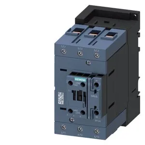
Siemens 3RT2448-1AL20 — Contactors

Siemens 3RT2448-1AL20 SIRIUS S3 Contactor, 152 mm depth

MPN3RT2448-1AL20
Active

Siemens SIRIUS S3 contactor, 3RT2448-1AL20, screw-type terminals, 152 mm depth, 70 mm width, 140 mm height, screw and snap-on mounting onto 35 mm DIN rail.

Sourced new & surplus through independent channelsAuthenticity-screened · ESD-safe packingListing updated Aug 2026

Specifications

3RT2448-1AL20 — Identification
ParameterValue
Contactor frame sizeS3
3RT2448-1AL20 — Ratings & Performance
ParameterValue
Rated operational current, AC-12, max.10 A
Rated value @ 400 V3 A
Rated value @ 500 V2 A
Rated value @ 690 V1 A
Rated value @ 230 V6 A
Rated value @ 24 V10 A
Rated value @ 60 V2 A
Rated value @ 110 V1 A
Rated value @ 220 V0.3 A
3RT2448-1AL20 — Control & Coil
ParameterValue
Control supply voltage typeAC
Rated value @ 50 Hz0.35
Rated value @ 50 Hz230 V
3RT2448-1AL20 — Contacts & Poles
ParameterValue
Main poles3
Main NO contacts3
Auxiliary contact reliability1 faulty switching per 100 million (17 V, 1 mA)
3RT2448-1AL20 — Protection & Coordination
ParameterValue
Short-circuit coordination type 1, fusegG: 250 A (690 V,100 kA)
Short-circuit coordination type 2, fusegR: 250 A (690 V, 100 kA)
Aux. switch short-circuit protection, fusegG: 10 A (500 V, 1 kA)
3RT2448-1AL20 — Connection & Mounting
ParameterValue
Main circuit connectionbox terminal
Aux. / control circuit connectionscrew-type terminals
Conductor cross-section, solid2x (0.5 ... 1.5 mm²), 2x (0.75 ... 2.5 mm²)
Conductor cross-section, solid or stranded2x (0.5 ... 1.5 mm²), 2x (0.75 ... 2.5 mm²)
Conductor cross-section, finely stranded w/ ferrule2x (0.5 ... 1.5 mm²), 2x (0.75 ... 2.5 mm²)
Mounting methodscrew and snap-on mounting onto 35 mm DIN rail according to DIN EN 60715
Side-by-side mountingYes
3RT2448-1AL20 — Durability
ParameterValue
Durability (operating cycles, typ.)10 000 000
Durability with aux. switch block (cycles, typ.)10 000 000
3RT2448-1AL20 — Environmental
ParameterValue
Operating temperature range-25 ... +60 °C
Storage temperature range-55 ... +80 °C
Installation altitude, max.2 000 m
3RT2448-1AL20 — Mechanical
ParameterValue
Width70 mm
Height140 mm
Depth152 mm
3RT2448-1AL20 — Specifications
ParameterValue
At AC10 ... 21 ms

Product details

Screw-type magnet coil terminals and power-side screw clamps accepting 6 to 70 mm² stranded wire mean you land the load cables without special tooling — common on 400 V distribution panels where ring lugs or pin ferrules are standard.

The 70 mm width and 140 mm height are the panel-space numbers. On a 600 x 400 mm backplate you can row-mount about eight of these side-by-side with 10 mm spacing — that is the fill factor a sourcing buyer needs to know before committing a BOM line. The mounting position flexibility (+/-180° rotation, +/-22.5° tilt on vertical surface,) means it can go into a swing-panel or a slanted cabinet without worrying about gravity pulling the armature out of alignment.

Frequently asked questions

Where can I buy 3RT2448-1AL20 and how do I get a price?

The 3RT2448-1AL20 is sourced to order against an RFQ through independent distribution. Submit a request for quote (RFQ) to receive current availability and pricing.

What is 3RT2448-1AL20's listed depth?

The 3RT2448-1AL20 has a listed depth of 152 mm, which is the critical dimension for enclosure depth selection and gland-plate clearance.

What wire sizes does the 3RT2448-1AL20 accept on the power side?

The power terminals accept stranded wire from 6 to 70 mm², while the auxiliary and coil terminals accept solid or stranded wire in two ranges: 2x (0.5 to 1.5 mm²) and 2x (0.75 to 2.5 mm²).

MPN
3RT2448-1AL20