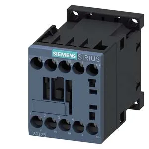
SIRIUS Size S00 Contactor with 24 VDC Coil
It mounts via screw or snap-on onto 35 mm DIN rail per DIN EN 50022, and the mounting position allows +/-180° rotation on a vertical surface, plus forward/backward tilt of +/-22.5°. This gives panel builders flexibility in tight enclosures, though side clearance of 6 mm is specified for heat dissipation when mounting side-by-side.
The auxiliary switch on this contactor carries DC ratings that drop significantly as voltage rises — a common constraint for DC switching. At 24 V it handles 10 A, but at 48 V that falls to 2 A, and at 110 V it's 1 A. At 220 V it's down to 0.3 A, and at 600 V only 0.1 A. These are the maximum currents the auxiliary contacts can interrupt at those DC voltages. If you're switching a 48 VDC control circuit, the 2 A rating is the limit; exceeding it risks welding the contacts.
The mechanical life of the contactor is typical 30,000,000 operations — this is the unloaded mechanical endurance, not the electrical life under load. Electrical life depends on the switching duty: at AC-1 (resistive load) the maximum switching rate is 1,000 operations per hour, while the general AC switching rate is 10,000 per hour. The coil pick-up and drop-out thresholds are specified as 0.8 x rated voltage for pick-up and 1.1 x rated voltage for drop-out — meaning at 24 VDC nominal, the coil will pick up at 19.2 V and drop out at 26.4 V.
Wiring and Integration
The screw-type terminals on the main circuit accept solid or stranded conductors: 2x 0.5 to 1.5 mm², 2x 0.75 to 2.5 mm², or 2x 4 mm². The coil terminals are also screw-type. The 45 mm width and 57.5 mm height with 73 mm depth make it a compact fit for a size S00 contactor — it occupies roughly the same footprint as a miniature circuit breaker. Side-by-side mounting is permitted, so multiple contactors can be ganged without spacing, provided the 6 mm side clearance to adjacent components is respected for thermal management.