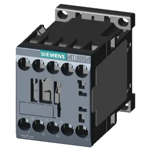
SIRIUS S00 Contactor for Panel Integration
It mounts via screw or snap-on onto 35 mm DIN rail per DIN EN 50022, and the mounting position allows +/-180° rotation on a vertical surface, plus +/-22.5° forward/backward tilt — useful when fitting into tight enclosures or aligning with busbar systems. The integrated auxiliary switch eliminates the need for a separate add-on block in many circuits, saving DIN-rail space.
The magnet coil uses screw-type terminals. The main circuit accepts solid or stranded conductors: 2x (0.5...1.5 mm²), 2x (0.75...2.5 mm²), or 2x 4 mm² per clamp. This range covers standard control wiring up to 4 mm² for power feeds.
Switching Capacity and Duty Cycles
Switching capacity is specified at multiple voltage levels: 10 A at 24 V, 10 A at 230 V, 3 A at 400 V, and 0.1 A at 600 V (–). The AC-1 maximum operating frequency is 1,000 cycles per hour, while DC switching is rated at 10,000 operations per hour. Arcing time spans 10–15 ms at AC, with a 4–15 ms at AC range for the coil.
The contactor measures 57.5 mm high, 45 mm wide, and 73 mm deep. Side-by-side mounting is supported, with a 6 mm side clearance required. Clearances above, below, forward, and backward are 0 mm, meaning it can be stacked tightly in a row.