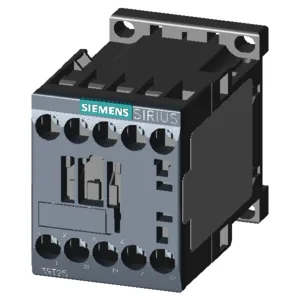
Spring-cage terminals on both the coil and the main/auxiliary circuits — no screwdriver needed for the power wiring, which speeds up panel assembly. The contactor snaps onto a 35 mm DIN rail (DIN EN 50022) or screws directly to a mounting plate, and the mounting position allows ±180° rotation on a vertical surface plus ±22.5° tilt forward/backward, so it fits tight enclosures without forcing the cable bend radius.
The built-in auxiliary switch is rated for 10 A at both 24 V and 230 V (50/60 Hz). That 10 A at 24 V is the number to check if you're driving a PLC input or a small relay coil — it's well above the typical 0.5–2 A draw of a modern digital input module, so contact wetting current is not a concern. At 48 V the rating drops to 2 A, at 110 V to 1 A, and at 400 V to 3 A. The non-linear curve reflects the arc-quenching limits in a DC circuit; if you're switching a 48 VDC solenoid, the 2 A ceiling is the binding constraint, not the 10 A at 24 V. That's roughly one cycle every 3.6 seconds — fine for a conveyor interlock or a valve manifold, but not for a high-speed pick-and-place station running at 10 Hz.
Panel Fit and Clearances
Side-by-side mounting is allowed with zero spacing between units — no derating for adjacent contactors in still air. Clearance to grounded metal: 6 mm to the side, 0 mm forward/backward/upward/downward, so you can pack them against the back panel and the gland plate. The spring-cage terminals accept 2 × (0.5 … 4 mm²) solid or stranded wire, which covers most control-circuit cable sizes up to 12 AWG.
Environmental Range
The -25 °C lower limit is worth noting for unheated warehouses or outdoor cabinets in cold climates — the coil must still pick reliably at that temperature with 24 VDC applied. The storage range is wider because the contactor is not under electrical stress, but the plastic housing and spring-cage mechanism are rated for those extremes.