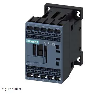
Siemens 3RT2518-2XF40-0LA2 — Contactors

Siemens 3RT2518-2XF40-0LA2 SIRIUS Contactor

MPN3RT2518-2XF40-0LA2

Siemens SIRIUS 3RT2518-2XF40-0LA2 power contactor, size S00, DC coil 72-125 V, spring-type terminals, 45 mm width, 73 mm depth, 70 mm height, screw and snap-on 35 mm DIN rail mounting.

Source DocumentedChannel stated on listing & quote
Condition PhotosReal unit photos / video on request
WhatsApp AnswersFast human replies for machine-down parts
Worldwide DispatchDHL/FedEx — transit quoted per order
Independent China distributor & sourcing agent· Listing updated Sep 2026

Specifications

3RT2518-2XF40-0LA2 — Identification
ParameterValue
Contactor frame sizeS00
3RT2518-2XF40-0LA2 — Ratings & Performance
ParameterValue
Rated operational current, AC-12, max.10 A
Rated operational current, AC-4 @ 400 V11.5 A
Rated value @ 400 V3 A
Rated value @ 500 V2 A
Rated value @ 690 V1 A
Rated value @ 230 V2 hp
Rated value @ 24 V10 A
Rated value @ 60 V2 A
Rated value @ 110 V1 A
Rated value @ 220 V0.3 A
3RT2518-2XF40-0LA2 — Control & Coil
ParameterValue
Control supply voltage typeDC
3RT2518-2XF40-0LA2 — Contacts & Poles
ParameterValue
Main poles4
Main NO contacts2
3RT2518-2XF40-0LA2 — Protection & Coordination
ParameterValue
Short-circuit coordination type 1, fusegG NH 3NA, DIAZED 5SB, NEOZED 5SE: 35 A
Short-circuit coordination type 2, fusegG NH 3NA, DIAZED 5SB, NEOZED 5SE: 20 A
Aux. switch short-circuit protection, fusegG: 10 A (500 V, 1 kA)
3RT2518-2XF40-0LA2 — Connection & Mounting
ParameterValue
Main circuit connectionspring-loaded terminals
Aux. / control circuit connectionspring-loaded terminals
Conductor cross-section, solid2x (0.5 ... 1.5 mm²), 2x (0.75 ... 2.5 mm²), 2x 4 mm²
Conductor cross-section, solid or stranded2x (0,5 ... 4 mm²)
Conductor cross-section, finely stranded w/ ferrule2x (0.5 ... 2.5 mm²)
Mounting methodscrew and snap-on mounting onto 35 mm DIN rail according to DIN EN 50022
Side-by-side mountingYes
3RT2518-2XF40-0LA2 — Durability
ParameterValue
Durability (operating cycles, typ.)30 000 000
Durability with aux. switch block (cycles, typ.)10 000 000
3RT2518-2XF40-0LA2 — Environmental
ParameterValue
Operating temperature range-40 ... +70 °C
Storage temperature range-55 ... +80 °C
Installation altitude, max.2 000 m
3RT2518-2XF40-0LA2 — Mechanical
ParameterValue
Width45 mm
Height70 mm
Depth73 mm

Product details

DC coil 72-125 V — pull-in margin and transformer loading

The 3RT2518-2XF40-0LA2: The DC coil is rated for 72 to 125 V DC. The pull-in voltage is 0.7 × rated value, so at a nominal 110 V DC bus the contactor pulls in reliably at 77 V — well within the typical battery sag during a station black-start sequence. The inrush current peak is 1.1 A; that spike loads the control transformer and the rectifier — if you are feeding multiple contactors from a common DC supply, sum the inrush peaks and check the transformer's regulation curve so the bus does not dip below the hold-in threshold. Hold-in power is lower than pull-in — the 0.7 factor applies to the initial pull-in only. Once sealed, the coil current drops to the holding value, which keeps the temperature rise inside the S00 envelope manageable even in a crowded 45 mm slot.

Switching capacity — AC motor and DC load break

For AC motor duty, the contactor is rated 2 hp at 230 V, 14 A at 480 V, and 11 A at 600 V. That derating is typical for DC arcs — the arcing time is 10-15 ms, and the DC arc extinguishes only when the current falls below the minimum arc current, so the contact gap and blowout design limit the DC rating. The main contacts are rated 20-12 A. This is the continuous thermal current (Ith) — the contactor can carry that current continuously in free air. In a sealed panel with multiple contactors side by side, derate per the manufacturer's grouping factor; the 45 mm width leaves little space for natural convection between units.

Spring terminals and wire range — panel wiring speed

The coil and auxiliary connections use spring-type terminals. The solid conductor range is 2×(0.5-1.5 mm²), 2×(0.75-2.5 mm²), and 2×4 mm². The main power terminals accept 2×(0.5-4 mm²) solid or stranded. Spring terminals eliminate the need for a screwdriver torque check — push the ferrule in until the cage clicks. For the 4 mm² power wires, use a ferrule sized for the strand class; the spring force is sufficient for Class 2 stranded but may not grip Class 5 flexible without a ferrule.

Mounting and clearance — DIN rail and enclosure fit

The height is 70 mm — check the DIN rail end-stop height if the rail is near the top of the enclosure.

MPN
3RT2518-2XF40-0LA2