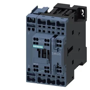
It is a current-production part, so you are not hunting for NOS or surplus — it is a standard catalog line. The S0 frame means it handles moderate motor and resistive loads in a compact footprint (61 mm wide, 102 mm high, 107 mm deep). The spring-type coil terminals save panel-build time versus screw-clamp — no torque driver needed on the coil circuit. Mounting is screw-and-snap onto 35 mm DIN rail per DIN EN 50022, with ±180° rotation possible on a vertical surface and ±22.5° tilt forward/backward. That gives you flexibility in tight enclosures without custom brackets.
Auxiliary contact ratings — the real switching limits
The built-in auxiliary switch is rated 10 A at 24 V and 230 V AC, but drops to 2 A at 48 V DC and 0.1 A at 600 V. The DC derating is steep — if you are switching a 48 VDC pilot light or solenoid, the 2 A limit is the one that governs, not the 10 A AC figure. At 110 VDC the rating is 1 A, and at 220 VDC it drops to 0.3 A. For any DC control circuit above 24 V, check the voltage-specific row — the AC-1 style rating does not carry over.
If you are comparing it to the 3RT2535-1AD00 (a larger-frame SIRIUS contactor), the 3RT2526-2BB40 will not drop into the same panel footprint without rewiring — the S0 frame is physically smaller and the terminal layout differs. Stick with the S0 frame for a direct swap.
Integration notes
The contactor accepts 2x (0.5 to 2.5 mm²) solid or stranded wire on the spring terminals. Strip length is standard for cage-clamp style — 8 to 10 mm. No ferrule required but recommended for stranded in high-vibration panels. The 0 mm clearance to adjacent devices on all sides except the side (6 mm) means you can pack S0 contactors tightly in a row for multi-motor groups.