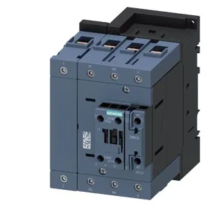
SIRIUS S3 contactor — panel fit and switching capability
It fastens via screw or snap-on onto 35 mm DIN rail per DIN EN 60715, and the mounting position allows ±180° rotation on a vertical surface plus ±22.5° tilt forward/backward — useful when fitting into a crowded enclosure where the rail orientation is fixed. The contactor envelope measures 152 mm deep by 70 mm wide by 140 mm high. Clearance requirements: 10 mm upwards, 0 mm forwards, 0 mm backwards, 10 mm downwards, and 10 mm at the side. That zero forward/backward gap means it can sit flush against a panel backplane or a neighbouring device, which simplifies layout in a tight row. Power-circuit wiring accepts stranded conductors: 2x (6…16 mm²), 2x (10…50 mm²), or 1x (10…70 mm²). Control-circuit terminals take solid or stranded 2x (0.5…1.5 mm²) or 2x (0.75…2.5 mm²). The 70 mm² single-conductor capacity on the power side is generous for an S3 frame — it can terminate a motor feeder without needing a separate terminal block for the line-side cable.
Auxiliary contact ratings across the voltage range
The built-in auxiliary switch is rated at 10 A at 24 V, 2 A at 48 V and 60 V, 1 A at 110 V, 0.9 A at 125 V, 0.3 A at 220 V, 6 A at 230 V, 3 A at 400 V, 1.8 A at 440 V, 2 A at 500 V, and 0.1 A at 600 V. These are the make/break capacities for the auxiliary contacts — they define what PLC input, relay coil, or indicator lamp this contactor can switch directly without an interposing relay. The 6 A at 230 V is notably higher than the 0.3 A at 220 V, so confirm the nominal voltage of the control circuit against the table before committing the BOM line. Switching times: AC operate time 11…21 ms, arcing time 10…20 ms. The arcing window matters for coordination with upstream short-circuit protection — a fuse or MCCB must hold through the 20 ms arc without nuisance tripping on a normal switching event.
Lifecycle and compliance posture
Operating temperature range is -25…+60 °C, storage range -55…+80 °C.