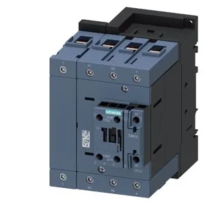
Panel fit: 70 mm wide, 152 mm deep, with specific clearance needs
The 3RT2545-1NP30: The mounting method accepts both screw fixing and snap-on — useful for retrofit into existing panels where the rail is already populated. Clearance requirements are 10 mm above and below, 10 mm to the sides, and zero forward or backward. The 10 mm side gap is the critical one for heat dissipation from the power poles; crowding closer than that derates the thermal capacity.
Coil: 175-280 V AC, 3.1 VA, with 65 A inrush peak
The coil is rated 175-280 V AC, 50/60 Hz, drawing 3.1 VA at both frequencies. That steady-state burden is low enough for a small control transformer, but the inrush peak hits 65 A — the PLC output or control relay driving this coil must handle that surge without welding contacts. Operate time is 38-57 ms on both AC and DC supplies, and the arcing time runs 10-20 ms. This consistency simplifies timing coordination with upstream motor-protective breakers or fuses.
Auxiliary contacts: ratings across common control voltages
An auxiliary switch is built in — no separate add-on block needed for basic status feedback. These numbers govern whether the contact can drive the downstream PLC input or indicator lamp without an interposing relay.
Wiring: screw terminals for power and control circuits
Power terminals accept stranded wire from 6 mm² up to 70 mm² (single conductor), or two conductors from 6-16 mm² and 10-50 mm². Control-circuit terminals take solid or stranded 0.5-2.5 mm², two per clamp. The screw-type coil terminals allow field replacement of the magnet coil without special tools.
Environmental limits: -25 to +60 °C operating, 10 million mechanical cycles
The mechanical endurance is 10 million cycles typical, and the maximum switching rate at AC-1 is 900 cycles per hour. For motor-load switching (AC-3), the electrical life will be lower and depends on the actual load current.