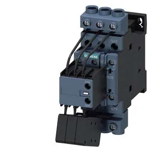
It's a dedicated piece — not a general-purpose contactor pressed into capacitor duty. The 24 V AC coil with screw-type terminals is the control interface. Rated for 6 A at 230 V, 3 A at 400 V, and 1 A at 690 V, so the switching capacity drops as voltage rises — that's the capacitor inrush curve, not a linear derating. Width is 45 mm, height 150 mm, depth 155 mm. That 45 mm footprint is tight for an S0 frame — leaves room on the rail for the upstream breaker and the controller.
Solid conductors accepted: 2x (0.5 to 1.5 mm²), 2x (0.75 to 2.5 mm²), or 2x 4 mm². Stranded: 2x (1 to 2.5 mm²) or 2x (2.5 to 10 mm²). That 10 mm² stranded max on the power path is generous for an S0 — handles the capacitor bank feed without needing a lug adapter. The screw-type terminals are the traditional field-proven interface; no push-in, but also no tool-specific requirement. The contactor has one instantaneous contact. Switching times at AC: 4 to 16 ms. Arcing time is 10 ms. Those numbers matter for coordinating with the upstream fuse or breaker — the arc has to clear before the OCPD sees the fault as a sustained event.
Operating Limits and Switching Frequency
Maximum switching frequency at 230 V, 240 V, and 400 V is 100 operations per hour. That drops to 70/h at 480 V, 65/h at 500 V, 45/h at 600 V, and 36/h at 690 V. The frequency limit is voltage-dependent because higher voltages mean longer arc extinction and more thermal stress on the contacts. For a capacitor bank that cycles with every power-factor correction step, 100/h is usually plenty — but if you're switching every 36 seconds at 400 V, you're at the limit.