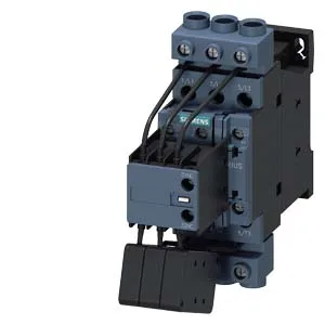
Siemens 3RT2628-1AP65 — Contactors

Siemens 3RT2628-1AP65 SIRIUS Capacitor Contactor, S0

MPN3RT2628-1AP65
Active

Siemens SIRIUS 3RT2628-1AP65 capacitor contactor, size S0, 45 mm width, 150 mm height, 155 mm depth, screw-type terminals, 230 V AC coil, 6 A switching current at 230 V, 3 A at 400 V, DIN rail mount.

Sourced new & surplus through independent channelsAuthenticity-screened · ESD-safe packingListing updated Aug 2026

Specifications

3RT2628-1AP65 — Identification
ParameterValue
Contactor frame sizeS0
3RT2628-1AP65 — Control & Coil
ParameterValue
Control supply voltage typeAC
Rated value @ 50 Hz0.8 ... 1.1
Rated value @ 50 Hz220 ... 220 V
3RT2628-1AP65 — Contacts & Poles
ParameterValue
Main poles3
Main NO contacts3
Auxiliary contact reliability0.00000001
3RT2628-1AP65 — Protection & Coordination
ParameterValue
Aux. switch short-circuit protection, fusegG: 10 A (500 V, 1 kA)
3RT2628-1AP65 — Connection & Mounting
ParameterValue
Main circuit connectionscrew-type terminals
Aux. / control circuit connectionscrew-type terminals
Conductor cross-section, solid2x (0.5 ... 1.5 mm²), 2x (0.75 ... 2.5 mm²), 2x 4 mm²
Conductor cross-section, solid or stranded2x (0.5 ... 1.5 mm²), 2x (0.75 ... 2.5 mm²), 2x 4 mm²
Conductor cross-section, finely stranded w/ ferrule2x (0.5 ... 1.5 mm²), 2x (0.75 ... 2.5 mm²)
Mounting methodscrew and snap-on mounting onto 35 mm DIN rail according to DIN EN 50022
3RT2628-1AP65 — Durability
ParameterValue
Durability with aux. switch block (cycles, typ.)3 000 000
3RT2628-1AP65 — Environmental
ParameterValue
Operating temperature range-25 ... +60 °C
Storage temperature range-55 ... +80 °C
Installation altitude, max.2 000 m
3RT2628-1AP65 — Mechanical
ParameterValue
Width45 mm
Height150 mm
Depth155 mm
3RT2628-1AP65 — Specifications
ParameterValue
At AC4 ... 16 ms

Product details

Capacitor switching duty — what the ratings deliver

The 3RT2628-1AP65: This is a SIRIUS capacitor contactor, purpose-built for switching power factor correction capacitor banks. These are the currents the contactor can make and break for capacitor loads — the inrush from charging capacitors can be 20-30x rated current, so the contactor's arc-chamber design handles that stress. The arcing time is a tight 10 ms typical, with AC switching time between 4 and 16 ms — fast enough for most capacitor switching cycles.

Switching frequency derating — the voltage-speed tradeoff

Maximum switching frequency drops as voltage rises: 100 operations per hour at 230/240/400 V, 70/h at 480 V, 65/h at 500 V, 45/h at 600 V, and 36/h at 690 V. This is the thermal limit of the contactor — pushing more cycles at higher voltage overheats the arc chamber. For PFC banks with frequent switching, stay under these ceilings. At 40 °C ambient, the maximum cable cross-section is 16 mm² solid; at 60 °C it drops to 25 mm² — the derating curve matters for panel wiring at the top of the enclosure. Stranded takes 2x (1-2.5 mm²) or 2x (2.5-10 mm²). Coil terminals are screw-type, rated for the 220-240 V AC coil at 50/60 Hz.

Mounting flexibility and panel integration

This means it fits in tight enclosures where the DIN rail is oriented oddly — but the contactor's internal arc path is designed for vertical orientation, so tilting beyond 22.5° may affect switching performance at high currents. No auxiliary contact blocks are attachable (0 attachable), so all auxiliary switching must come from external relays or the PLC output. Plan for that in the BOM.

Frequently asked questions

What does the 6 A at 230 V rating mean for capacitor bank sizing?

For a 230 V single-phase capacitor bank, this corresponds to roughly 1.4 kVAR (6 A × 230 V). At 400 V three-phase, the 3 A rating supports about 2 kVAR per phase. The contactor's inrush capability handles the capacitor charging surge, but the thermal rating sets the steady-state limit.

MPN
3RT2628-1AP65