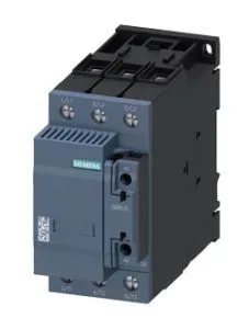
The 3RT2636-1NF35: The coil accepts AC or DC control voltage across a 83...155 V range, which covers common 110-120 V control circuits without needing a separate coil variant. This simplifies BOM consolidation when your panel runs mixed AC and DC control power.
Termination and wiring capacity
Main power circuit terminals accept stranded conductors: 2x (10...35 mm²) or a single 1x (10...50 mm²). This covers typical motor feeder sizes up to 50 mm² for the line and load side, matching the conductor cross-section to the contactor's current rating without requiring a separate terminal adapter. The 65 mm width and 114 mm height fit a standard 65 mm-wide DIN-rail footprint, leaving room for adjacent overload relays and busbars in a typical motor starter row. Depth of 130 mm means the contactor protrudes 130 mm from the rail — check enclosure depth clearance before laying out the gland plate.
Switching performance and duty cycle
Arcing time is 10...20 ms, and the contactor can achieve up to 100 operating cycles per hour at 230-400 V. At higher voltages the maximum switching frequency drops — 60/h at 480 V, 55/h at 500 V, 40/h at 600 V, and 30/h at 690 V (-). This derating is driven by arc energy and contact wear; if your application cycles a motor at 690 V more than 30 times per hour, the contactor will exceed its rated electrical life. This covers most panel orientations except horizontal rail mounting — the contactor must be on a vertical plane for proper arc extinction.