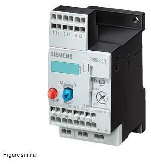
The 3RU1116-0FC1: Trip Class 10 means it will trip within 10 seconds at 7.2× the thermal current setting — standard for general-purpose motor starting where the load is not high-inertia. The relay mounts stand-alone on a vertical surface with ±135° rotation and ±45° tilt, giving flexibility in panel layout. Clearance requirements are tight: 0 mm upwards, forwards, backwards, and downwards, with only 6 mm needed at the side. This allows dense packing in a control cabinet without derating.
Both the main current circuit and the auxiliary/control circuit use Cage Clamp terminals. The main contacts accept 2x (0.5... 2.5 mm²) solid or 2x (0.5... 1.5 mm²) finely stranded with ferrule; equivalent AWG is 2x (24... 14). Auxiliary contacts accept 2x (20... 14) AWG. Power dissipation per pole is 1.6 W — factor this into the thermal budget of a densely populated panel.
Rated for operation from -20 to +70 °C, storage and transport from -55 to +80 °C, and 100% relative humidity during operation. Shock resistance is 8g for 10 ms. Approved for explosive atmospheres under DMT 98 ATEX G 001. Substance prohibitance date is July 1, 2006, aligning with RoHS requirements.
The auxiliary contact ratings are specified across multiple voltages: 1 A at 24 V, 0.22 A at 110 V, 3 A at 120 V, 0.22 A at 125 V, 0.11 A at 220 V, 2 A at 230 V, and 1 A at 400 V. These are the switching capacities for the built-in auxiliary contacts — match them to your control circuit load.