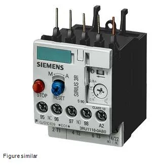
Siemens 3RU1116-1CB0-ZW96 — SIRIUS thermal overload relay, size S00, CLASS 10
The relay mounts directly to a contactor (contactor mounting per), so it integrates as a single assembly on the DIN rail, saving panel width. Front-side IP20 protection means the terminals are finger-safe when the panel door is open.
The 3RU1116-1CB0-ZW96 carries a surge voltage resistance of 6 kV, which means it withstands the transient overvoltages typical in industrial motor circuits without flashover — important for panels fed from a 400 V distribution system where switching surges can exceed 2.5 kV. The auxiliary contact ratings are given at multiple control voltages: 1 A at 24 V, 3 A at 120 V, 2 A at 230 V, and 1 A at 400 V. These are the make/break capacities for the N/O and N/C auxiliary contacts that signal the trip condition to a PLC or safety circuit. For a 24 VDC control loop, the 1 A rating is ample for driving a PLC input or a small contactor coil; at 230 VAC the 2 A rating covers most pilot-duty loads. The relay is ATEX certified (DMT 98 ATEX G 001,), which qualifies it for installation in potentially explosive atmospheres — typically Zone 2 or Zone 22 gas/dust areas in chemical, pharmaceutical, or grain-handling lines. The 100 % relative humidity rating means it can be installed in unconditioned enclosures or washdown zones without condensation-related failure, as long as the IP20 front is respected.
The relay measures 45 mm wide × 87 mm high × 78 mm deep. The 78 mm depth is the dimension from the mounting surface to the furthest projection — critical when fitting into a shallow enclosure or when a contactor is mounted behind a door. Clearance requirements: 0 mm upwards, 0 mm forwards, 0 mm backwards, 0 mm downwards, and 6 mm at the side. This means the relay can be stacked directly against adjacent devices vertically and forward/backward, with only 6 mm side gap needed for heat dissipation. The mounting position allows rotation of ±135° and tilting of ±45° front/back from vertical, so it fits in angled or space-constrained panels. Main circuit terminals accept solid conductors: 2× (0.5…1.5 mm²) and 2× (0.75…2.5 mm²), with AWG equivalents of 2× (20…16) and 2× (18…14) plus 2× 12. Auxiliary/control circuit terminals accept 2× (20…16) and 2× (18…14) AWG. Finely stranded conductors with core-end processing are also supported at the same cross-sections. All terminals are screw-type, so a standard Pozidriv or slotted screwdriver is all that is needed for installation — no special crimp tools beyond standard ferrules.