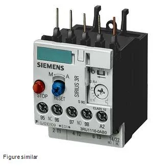
It mounts directly onto a contactor via the contactor mounting fastening method, saving DIN-rail space and simplifying wiring in the motor starter assembly.
The 3-pole configuration covers all three phases of the main current circuit, so a single device provides overload and phase-loss protection on a three-phase motor. The relay is ATEX approved under DMT 98 ATEX G 001, which certifies it for use in potentially explosive gas atmospheres. This Ex marking is the deciding factor for oil-and-gas or chemical-plant panels: confirm the Ex marking against your zone classification before specifying, per IEC 60079. Shock resistance of 8g for 10 ms is typical for industrial panel mounting on a contactor — it will hold calibration under normal vibration but not under repeated hammering.
Size S00 dimensions are 45 mm wide, 87 mm high, and 78 mm deep — compatible with the SIRIUS 3RT2 contactor series of the same frame size. The contactor mounting method clips the relay directly onto the contactor without additional DIN-rail space; the mounting position allows ±135° rotation and ±45° tilt on a vertical surface, giving panel builders flexibility in orientation. This tight clearance envelope means the relay can be packed closely with adjacent devices, though the 6 mm side gap must be maintained for heat dissipation during Class 10 tripping events. Screw-type terminals on both main and auxiliary circuits accept solid conductors: 2×(0.5…1.5 mm²) and 2×(0.75…2.5 mm²), with AWG equivalents for the main contacts: 2×(20…16), 2×(18…14), and 2×12. The auxiliary circuit terminals accept 2×(20…16) and 2×(18…14) AWG. Finely stranded conductors with core end processing use the same cross-section ranges.
Compliance documentation includes ATEX certificate DMT 98 ATEX G 001. The substance prohibitance date of 07/01/2006 aligns with RoHS compliance (EU RoHS effective July 2006).