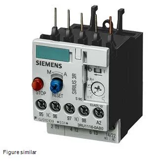
Thermal Overload Relay for SIRIUS Contactor Systems
It provides motor protection with CLASS 10 trip characteristics. Rated for 3-pole main circuits with screw-type terminals on both the main and auxiliary/control circuits. Mounts directly to the contactor via the fastening method specified as contactor mounting, with a vertical mounting surface that allows ±135° rotation and ±45° tilt forward/backward — useful for tight panel layouts where the contactor assembly must be oriented to fit cable ducts or busbars.
Contact Ratings and Auxiliary Circuit
The auxiliary contact block carries rated currents that vary by control voltage: 3 A at 120 V, 2 A at 230 V, 1 A at 400 V, and 1 A at 24 V. Power dissipation per pole is 1.9 W, so total heat load in the enclosure is 5.7 W under continuous rated current — factor that into your panel thermal budget, especially in a sealed cabinet.
Rated for 100 % relative humidity during operation — condensation is acceptable as long as the enclosure is rated for it. Carries ATEX type protection DMT 98 ATEX G 001, so it is approved for use in potentially explosive gas atmospheres when paired with an appropriate motor and enclosure. Surge voltage resistance is rated at 6 kV, and shock resistance at 8g for 10 ms. Substance prohibition date is 07/01/2006, indicating RoHS compliance per the EU directive effective that date.
Main circuit terminals accept solid or finely stranded conductors with core-end processing: 2×(0.5…1.5 mm²) and 2×(0.75…2.5 mm²). AWG equivalents are 2×(20…16) and 2×(18…14), plus 2×12 AWG. Auxiliary contacts accept 2×(20…16) and 2×(18…14) AWG. Clearance distances: 0 mm upwards, forwards, and backwards; 6 mm at the side; 0 mm downwards. The zero-clearance top and bottom allow stacking contactors and relays in a tight vertical column without additional spacing.