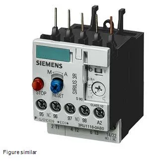
The IP20 front protection keeps live parts safe during panel access, and the ATEX certification (DMT 98 ATEX G 001) qualifies it for potentially explosive atmospheres where motor overload protection must meet directive requirements.
What Trip Class 10 means for motor protection
That's the standard for standard-duty induction motors — pumps, fans, compressors — where the rotor can handle a brief locked-rotor event without damage. For higher-inertia loads (flywheels, crushers) you'd typically step up to Class 20 or 30; for submersible pumps or hermetic compressors, Class 10 is often the spec. The 3RU1116-1GB0-ZX95's 3-pole design covers all three phases, so a single-phase condition or phase imbalance trips the relay.
This relay fastens directly to the contactor (contactor mounting per), saving DIN-rail space. The Size S00 body measures 45 mm wide, 87 mm high, and 78 mm deep — compact enough for crowded subpanels. Clearance requirements: 0 mm upwards, forwards, and backwards; 6 mm at the sides; 0 mm downwards — meaning it can stack tight against adjacent components in a row.
Environmental and electrical ratings
The relay withstands 100% relative humidity during operation — no condensation concern in washdown or coastal environments. Shock resistance is 8g for 10 ms, covering most industrial vibration profiles. Surge voltage resistance is rated at 6 kV, matching IEC 60947-1 coordination requirements for 400 VAC systems. Auxiliary contact ratings: 1 A at 24 V, 3 A at 120 V, 2 A at 230 V, 1 A at 400 V — sufficient for PLC inputs or contactor hold coils.
Wiring and terminal capacity
Main circuit accepts solid conductors: 2× (0.5…1.5 mm²) and 2× (0.75…2.5 mm²), plus AWG equivalents 2× (20…16) and 2× (18…14) and 2× 12. Finely stranded with core-end processing uses the same cross-sections. Auxiliary contacts take 2× (20…16) and 2× (18…14) AWG. The dual-wire capacity per clamp is useful for daisy-chaining control power or looping through the overload's NC contact to the contactor coil.