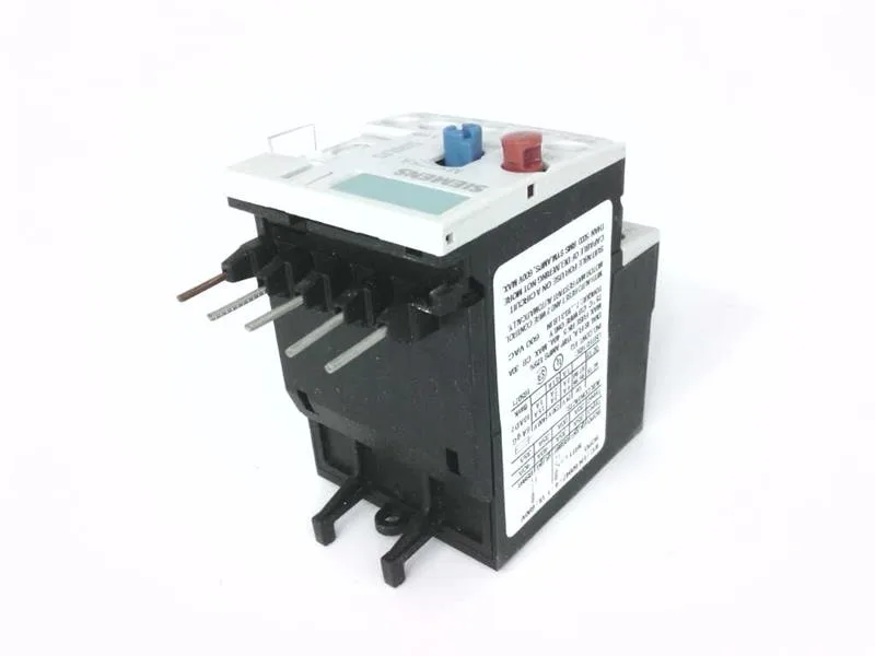
Siemens 3RU1116-1JB0-ZW96 — Overload Relays

Siemens 3RU1116-1JB0-ZW96 SIRIUS Thermal Overload Relay, Cla

MPN3RU1116-1JB0-ZW96

Siemens SIRIUS 3RU1116-1JB0-ZW96 thermal overload relay, S00 frame, Class 10 trip, 3-pole, screw terminals, IP20 front, ATEX certified.

Source DocumentedChannel stated on listing & quote
Condition PhotosReal unit photos / video on request
WhatsApp AnswersFast human replies for machine-down parts
Worldwide DispatchDHL/FedEx — transit quoted per order
Independent China distributor & sourcing agent· Listing updated Sep 2026

Specifications

3RU1116-1JB0-ZW96 — Identification
ParameterValue
Product brand nameSIRIUS
Product designationthermal overload relay
Frame size (overload relay)S00
Combinable contactor sizesS00
Reference code (IEC 81346-2)F
3RU1116-1JB0-ZW96 — Protection & Trip
ParameterValue
Overload current setting range7 ... 10 A
Trip classCLASS 10
3RU1116-1JB0-ZW96 — Electrical (main circuit)
ParameterValue
Poles (main circuit)3
Rated insulation voltage (AC, pollution degree 3)690 V
Rated surge withstand voltage6 kV
Main current circuitscrew-type terminals
Power loss at rated current (hot)6.6 W
Per pole2.2 W
3RU1116-1JB0-ZW96 — Auxiliary contacts
ParameterValue
Auxiliary contacts: NO1
Auxiliary contacts: NC1
Auxiliary contacts: CO (changeover)0
Auxiliary switch short-circuit protection (required fuse)fuse gL/gG: 6 A, quick: 10 A
Switching current at 24 V1 A
Switching current at 110 V0.22 A
Switching current at 120 V3 A
Switching current at 125 V0.22 A
Switching current at 220 V0.11 A
Switching current at 230 V2 A
Switching current at 400 V1 A
3RU1116-1JB0-ZW96 — Connection & Mounting
ParameterValue
Mounting / fastening methodContactor mounting
Mounting positionwith vertical mounting surface +/-135° rotatable, with vertical mounting surface +/- 45° tiltable to the front and back
Auxiliary/control circuit connection typescrew-type terminals
Removable aux./control terminalNo
Conductor cross-section: solid2x (0.5 ... 1.5 mm²), 2x (0.75 ... 2.5 mm²)
Conductor cross-section: finely stranded with ferrule2x (0.5 ... 1.5 mm²), 2x (0.75 ... 2.5 mm²)
3RU1116-1JB0-ZW96 — Environmental
ParameterValue
Operating temperature-20 ... +70 °C
Storage temperature-55 ... +80 °C
Transport temperature-55 ... +80 °C
Relative humidity, operating100 %
Max. installation altitude2 000 m
Shock resistance8g / 10 ms
3RU1116-1JB0-ZW96 — Mechanical
ParameterValue
Width45 mm
Height87 mm
Depth78 mm
3RU1116-1JB0-ZW96 — Specifications
ParameterValue
Type Of ProtectionDMT 98 ATEX G 001

Product details

The S00 frame size tells you it mates with the S00 contactor family and handles motor FLCs in the lower range of the SIRIUS line.

Mounts directly onto the contactor — the fastening method is contactor mounting, so no DIN rail bracket needed if you're snapping it onto a S00 contactor. The dimensions are compact: 45 mm wide, 87 mm tall, and 78 mm deep. That depth matters when you're calculating gland-plate clearance or panel-door swing. Side clearance to adjacent devices is 6 mm; zero clearance needed upwards, forwards, backwards, or downwards.

Terminals and wiring

Both main and auxiliary/control circuits use screw-type terminals. The solid wire capacity is 2× (0.5 … 1.5 mm²) and 2× (0.75 … 2.5 mm²); finely stranded with core-end processing matches the same ranges. For AWG on the auxiliary contacts, it accepts 2× (20 … 16) and 2× (18 … 14). That's enough for standard motor-circuit wiring and control-loop conductors. The front is finger-safe per IP20 — touch-safe for the panel builder but not for washdown environments.

Ratings that matter for the panel

Power dissipation is 2.2 W per pole — three poles means 6.6 W total heat to manage inside the enclosure. That's modest, but if you're packing a dozen of these in a sealed box, the thermal rise adds up. Auxiliary contact ratings: 1 A at 24 V, 3 A at 120 V, 2 A at 230 V, 1 A at 400 V. These are the currents the built-in auxiliary switch can break — useful for signaling the PLC or a status lamp. Shock resistance is 8g for 10 ms — fine for machine-mounted applications with moderate vibration.

Frequently asked questions

What compliance documentation does this part carry?

It carries ATEX approval DMT 98 ATEX G 001 for explosive gas atmospheres, is RoHS-compliant per substance prohibition date 07/01/2006, and has IP20 touch protection on the front. The reference code per IEC 81346-2 is F.

What are the key dimensions for panel layout?

Width is 45 mm, height is 87 mm, depth is 78 mm. Side clearance needed is 6 mm; zero clearance required upwards, forwards, backwards, or downwards.

What wire sizes does the terminal block accept?

Solid conductors: 2× (0.5 … 1.5 mm²) and 2× (0.75 … 2.5 mm²). Finely stranded with core-end processing matches the same ranges. For AWG on auxiliary contacts: 2× (20 … 16) and 2× (18 … 14). Both main and auxiliary circuits use screw-type terminals.

What does CLASS 10 mean on this overload relay?

CLASS 10 means the relay will trip within 10 seconds at 7.2 times the set current. This is the standard trip class for standard-duty induction motors — it protects the motor from sustained overload without nuisance-tripping during normal starting.

MPN
3RU1116-1JB0-ZW96