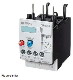
Mounting is via direct contactor attachment (fastening method: contactor mounting), so it snaps onto the matching SIRIUS contactor without additional DIN-rail space. The relay carries DMT 98 ATEX G 001 certification, meaning it is approved for use in potentially explosive gas atmospheres — a requirement for Zone 1 or Zone 2 motor circuits in chemical, oil-and-gas, or grain-handling plants. The front panel is IP20 rated, finger-safe per IEC 60529, so it can sit on an open panel door without additional guarding.
If your motor has a longer acceleration time (high-inertia loads like centrifuges or large flywheels), you would typically step up to CLASS 20 or CLASS 30 — but that is a different relay, not this one. The S0 frame size is the mid-range in the SIRIUS family, physically fitting contactors in the same S0 envelope. Clearance requirements: 0 mm upward, forward, backward, and downward; 6 mm at the side. That zero-clearance top and bottom means you can stack contactors directly without leaving an air gap, but the 6 mm side gap must be maintained for heat dissipation. The solid/stranded wire range is 2× (0.5…1.5 mm²) and 2× (0.75…2.5 mm²) for the auxiliary contacts, with AWG equivalents of 2× (20…16) and 2× (18…14). For the main circuit, the same ranges apply. This covers most control wiring up to 2.5 mm² — standard for motor control centers. Auxiliary contact ratings: at 24 V it switches 1 A; at 120 V, 3 A; at 230 V, 2 A; at 400 V, 1 A.
Environmental and electrical robustness
Relative humidity during operation can hit 100% — no derating needed for condensing environments, which is common in washdown or outdoor installations. Shock resistance is 8g for 10 ms, adequate for most industrial vibration profiles (pumps, conveyors, compressors). Surge voltage withstand is rated at 6 kV, which matches the impulse voltage category for 400 V industrial circuits (overvoltage category III per IEC 60664). This means the relay can handle switching transients from contactor coils and motor starts without internal flashover. Heat dissipation per pole is 2.2 W. For a three-pole relay at full load, that is 6.6 W total — modest, but in a densely packed panel with multiple relays side by side, the cumulative heat can raise ambient temperature above the 70 °C limit. The 6 mm side clearance is the critical spacing to keep that heat manageable.