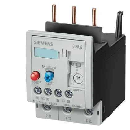
It mounts directly onto a contactor, using the contactor mounting method, which means it shares the same DIN-rail footprint as the matching contactor — no extra panel space needed beyond the contactor's own width of 55 mm.
The screw-type terminals on both the main and auxiliary/control circuits accept a wide range of conductors: stranded wire from 0.75 to 35 mm² on the main circuit, and solid wire from 0.5 to 2.5 mm² on the auxiliary side. That covers most motor power and control wiring you'd see in a standard panel. The auxiliary contact ratings are given for several control voltages: 1 A at 24 V, 3 A at 120 V, 2 A at 230 V, and 1 A at 400 V. These are the switching capacities for the N/O and N/C auxiliary contacts that signal the trip condition back to the PLC or starter circuit. The relay is ATEX certified (DMT 98 ATEX G 001), which qualifies it for use in potentially explosive atmospheres — a key differentiator for applications in chemical, oil and gas, or grain handling where standard overloads won't pass muster.
Mounting and Clearance Notes
The relay mounts directly onto the contactor — no separate DIN-rail clip needed. Clearance requirements are tight: 0 mm upwards, forwards, backwards, and downwards from the relay body, with only 6 mm needed at the side. That means it can be packed into a panel with minimal air gap around it, as long as the contactor itself has adequate ventilation. The mounting position allows rotation of ±135° and tilting of ±45° front-to-back on a vertical surface, giving flexibility in panel layout. Shock resistance is rated at 8g for 10 ms, which is adequate for most industrial machinery but not for high-vibration applications like crushers or reciprocating compressors — those may need a separate vibration-dampened mounting.