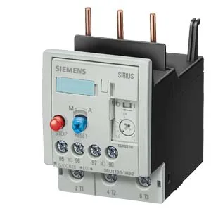
Siemens 3RU1136-4EB0-ZW98 — Overload Relays

Siemens 3RU1136-4EB0-ZW98 SIRIUS Thermal Overload Relay, Siz

MPN3RU1136-4EB0-ZW98

Siemens SIRIUS thermal overload relay, 3RU1136-4EB0-ZW98, Size S2, Trip Class 10, screw-type terminals, contactor mounting, IP20 front protection.

Source DocumentedChannel stated on listing & quote
Condition PhotosReal unit photos / video on request
WhatsApp AnswersFast human replies for machine-down parts
Worldwide DispatchDHL/FedEx — transit quoted per order
Independent China distributor & sourcing agent· Listing updated Sep 2026

Specifications

3RU1136-4EB0-ZW98 — Identification
ParameterValue
Product brand nameSIRIUS
Product designationthermal overload relay
Frame size (overload relay)S2
Combinable contactor sizesS2
Reference code (IEC 81346-2)F
3RU1136-4EB0-ZW98 — Protection & Trip
ParameterValue
Overload current setting range22 ... 32 A
Trip classCLASS 10
3RU1136-4EB0-ZW98 — Electrical (main circuit)
ParameterValue
Poles (main circuit)3
Rated insulation voltage (AC, pollution degree 3)690 V
Rated surge withstand voltage6 kV
Main current circuitscrew-type terminals
Power loss at rated current (hot)13.8 W
Per pole4.6 W
3RU1136-4EB0-ZW98 — Auxiliary contacts
ParameterValue
Auxiliary contacts: NO1
Auxiliary contacts: NC1
Auxiliary contacts: CO (changeover)0
Auxiliary switch short-circuit protection (required fuse)fuse gL/gG: 6 A, quick: 10 A
Switching current at 24 V1 A
Switching current at 110 V0.22 A
Switching current at 120 V3 A
Switching current at 125 V0.22 A
Switching current at 220 V0.11 A
Switching current at 230 V2 A
Switching current at 400 V1 A
3RU1136-4EB0-ZW98 — Connection & Mounting
ParameterValue
Mounting / fastening methodContactor mounting
Mounting positionwith vertical mounting surface +/-135° rotatable, with vertical mounting surface +/- 45° tiltable to the front and back
Auxiliary/control circuit connection typescrew-type terminals
Removable aux./control terminalNo
Conductor cross-section: solid2x (0.5 ... 1.5 mm²), 2x (0.75 ... 2.5 mm²)
Conductor cross-section: finely stranded with ferrule2x (0.5 ... 1.5 mm²), 2x (0.75 ... 2.5 mm²)
Conductor range (AWG), main contacts2x (18 ... 3), 1x (18 ... 1)
Conductor range (AWG), auxiliary contacts2x (20 ... 16), 2x (18 ... 14)
3RU1136-4EB0-ZW98 — Environmental
ParameterValue
Operating temperature-20 ... +70 °C
Storage temperature-55 ... +80 °C
Transport temperature-55 ... +80 °C
Relative humidity, operating100 %
Max. installation altitude2 000 m
Shock resistance8g / 10 ms
3RU1136-4EB0-ZW98 — Mechanical
ParameterValue
Width55 mm
Height105 mm
Depth118 mm
3RU1136-4EB0-ZW98 — Specifications
ParameterValue
Type Of ProtectionDMT 98 ATEX G 001

Product details

Trip Class 10 is the deciding factor for motor protection coordination. It matches the thermal characteristic of most standard squirrel-cage induction motors during start-up, allowing them to accelerate without nuisance tripping while still protecting against overload. If your motor has a longer acceleration time (high-inertia loads like centrifuges), you'd need a Class 20 or 30 relay — but for the majority of conveyor, pump, and fan applications, Class 10 is the right call. The Size S2 form factor is the mechanical interface. It mounts directly onto the corresponding S2 contactor (e.g., the 3RT1036 series), so the assembly clips together without additional hardware. Auxiliary contact ratings are given for several control voltages: 1 A at 24 V, 3 A at 120 V, 2 A at 230 V, and 1 A at 400 V. The 3 A at 120 V rating is the one most often used in North American control panels; the 1 A at 24 V covers the DC control common in European designs. Power dissipation is 4.6 W per pole. In a multi-motor panel with several relays, that heat adds up — account for it in your enclosure thermal calculation to avoid derating adjacent components.

Main circuit terminals accept stranded wire from 0.75 to 35 mm² (or 2x 0.75 to 25 mm²), and AWG from 18 to 1. Auxiliary circuit terminals take solid wire 2x 0.5 to 1.5 mm² or 2x 0.75 to 2.5 mm², and AWG 2x 20 to 16 or 2x 18 to 14. That covers the range from control wiring up to the motor feeder — no adapter lugs needed for standard installations. Clearance distances are specified: 0 mm upwards, forwards, backwards, and downwards, with 6 mm at the side. This means the relay can be stacked directly against adjacent devices vertically and horizontally as long as the side gap is maintained — typical for DIN-rail or mounting-plate layouts where space is at a premium.

The 100% relative humidity rating during operation means it's suitable for unconditioned indoor environments — no condensation, but high ambient moisture is acceptable. Shock resistance is 8g for 10 ms, which covers most industrial vibration from contactors and motors in the same panel. The substance prohibition date of 07/01/2006 aligns with RoHS compliance for the European market.

Frequently asked questions

What contactor does this relay mount on?

This Size S2 relay mounts directly onto the corresponding S2 contactor frame, such as the 3RT1036 series. The contactor-mounting fastening method means no separate base or wiring between the relay and contactor — it clips on and the main circuit passes through the relay's current transformers.

What are the key auxiliary contact ratings?

The auxiliary contacts are rated 1 A at 24 V, 3 A at 120 V, 2 A at 230 V, and 1 A at 400 V. These are the switching capacities for the trip-indication and control signals. The 3 A at 120 V rating is the highest and covers most North American control circuits.

What compliance documentation is available?

The relay carries ATEX certification (DMT 98 ATEX G 001) for use in potentially explosive atmospheres, and the substance prohibition date of 07/01/2006 indicates RoHS compliance. The IP20 front protection and 6 kV surge voltage resistance are standard for industrial control panels.

MPN
3RU1136-4EB0-ZW98