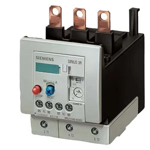
The 3RU1146-4FB0-ZX95: The relay measures 70 mm wide by 120 mm high by 140 mm deep. It mounts on a vertical surface with ±135° rotatability and ±45° tilt to front and back. Clearance requirements: 0 mm upwards, forwards, and backwards; 6 mm at the sides. This zero-clearance design on three sides simplifies panel layout when ganging multiple overloads next to each other.
Main circuit terminals accept screw-type connections: stranded wire from 2x (10 to 50 mm²) or single 10 to 70 mm², with AWG equivalents of 2x (10 to 1/0) or 1x (10 to 2/0). Auxiliary and control circuit terminals take solid wire 2x (0.5 to 1.5 mm²) or 2x (0.75 to 2.5 mm²), and AWG 2x (20 to 16) or 2x (18 to 14). This range covers most motor circuit wiring from fractional-horsepower up to moderate industrial loads.
Environmental and Protection Ratings
It withstands 100% relative humidity during operation and shock loads of 8g for 10 ms. The relay carries ATEX approval DMT 98 ATEX G 001, allowing use in potentially explosive atmospheres when properly integrated.
Coordination and Protection Data
With type of coordination 1, the relay requires a gG fuse rated 160 A upstream. For type of coordination 2, the requirement drops to 80 A gG. Power dissipation per pole is 4.5 W. These figures matter when sizing upstream protection and calculating panel thermal load.
Auxiliary contacts carry 1 A at 24 V, 3 A at 120 V, 2 A at 230 V, and 1 A at 400 V. For DC control circuits, ratings are 0.22 A at 110 V, 0.22 A at 125 V, and 0.11 A at 220 V. These values define the signal switching capability for PLC inputs or indicator lamps in the control circuit.