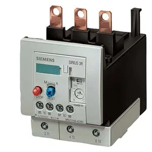
It is a CLASS 10 device, meaning it trips within 10 seconds at 7.2× the current setting, which is the standard for standard-capability motors that don't need the faster CLASS 5 or the slower CLASS 20. This is a Size S3 unit, the mid-range frame in the SIRIUS family, sized for motor loads that fit the S3 contactor footprint.
The trip class is the headline rating here: CLASS 10 means it clears a locked-rotor condition fast enough to protect the motor winding but not so fast that it nuisance-trips on normal starting inrush. For a pump or fan with a moderate start time, this is the right call. The relay carries a surge voltage resistance of 8 kV, which tells you the insulation coordination is built for industrial mains with transient activity — no external surge suppressor needed for the relay itself.
This relay mounts directly onto the contactor — the evidence lists "contactor mounting" as the fastening method. No DIN rail bracket is involved; it clips onto the S3 contactor's body and connects through the main power terminals. That means it can be oriented to fit tight panel layouts without derating, as long as the vertical surface requirement is met. Depth is 140 mm, width 70 mm, height 120 mm — the depth is the dimension that extends forward from the contactor face, so plan for that clearance in the enclosure depth.
Main circuit terminals are screw-type, accepting stranded conductors from 10 to 70 mm² or 2x (10 to 50 mm²). For AWG, that translates to 2x (10 to 1/0) or 1x (10 to 2/0). Auxiliary and control circuit terminals are also screw-type, accepting solid conductors 2x (0.5 to 1.5 mm²) and 2x (0.75 to 2.5 mm²), or AWG 2x (20 to 16) and 2x (18 to 14). The solid conductor range is what a VMI coordinator or panel builder needs to confirm for the control wiring gauge already in the panel — if the existing control wires are 1.5 mm² solid, they fit; if they are 4 mm², they don't.
Protection and compliance
The relay holds ATEX certification DMT 98 ATEX G 001, which qualifies it for use in potentially explosive gas atmospheres when paired with the correct contactor and upstream protection. For fuse coordination, with type of coordination 2 required the upstream gG fuse is 125 A; with type of coordination 1 required it is 200 A. That is the fuse size the panel designer needs to spec upstream to guarantee the relay clears a fault without damage to itself. Shock resistance is 8g for 10 ms — sufficient for normal industrial vibration but not for high-impact applications like forging presses.