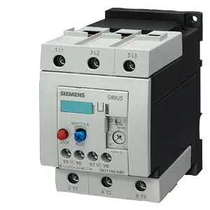
Siemens 3RU1146-4JB1 — Overload Relays

Siemens 3RU1146-4JB1 SIRIUS thermal overload relay, S3, Clas

MPN3RU1146-4JB1

Siemens SIRIUS 3RU1146-4JB1 thermal overload relay, size S3, screw-type terminals, Class 10 trip, 125 A gG coordination, ATEX certified, IP20 front protection.

Source DocumentedChannel stated on listing & quote
Condition PhotosReal unit photos / video on request
WhatsApp AnswersFast human replies for machine-down parts
Worldwide DispatchDHL/FedEx — transit quoted per order
Independent China distributor & sourcing agent· Listing updated Sep 2026

Specifications

3RU1146-4JB1 — Identification
ParameterValue
Product brand nameSIRIUS
Product designationthermal overload relay
Frame size (overload relay)S3
Combinable contactor sizesS3
Reference code (IEC 81346-2)F
3RU1146-4JB1 — Protection & Trip
ParameterValue
Overload current setting range45 ... 63 A
Trip classCLASS 10
3RU1146-4JB1 — Electrical (main circuit)
ParameterValue
Poles (main circuit)3
Rated insulation voltage (AC, pollution degree 3)1 000 V
Rated surge withstand voltage8 kV
Main current circuitscrew-type terminals
Power loss at rated current (hot)17.1 W
Per pole5.7 W
3RU1146-4JB1 — Auxiliary contacts
ParameterValue
Auxiliary contacts: NO1
Auxiliary contacts: NC1
Auxiliary contacts: CO (changeover)0
Auxiliary switch short-circuit protection (required fuse)fuse gL/gG: 6 A, quick: 10 A
Switching current at 24 V1 A
Switching current at 110 V0.22 A
Switching current at 120 V3 A
Switching current at 125 V0.22 A
Switching current at 220 V0.11 A
Switching current at 230 V2 A
Switching current at 400 V1 A
3RU1146-4JB1 — Connection & Mounting
ParameterValue
Mounting / fastening methodstand-alone installation
Mounting positionwith vertical mounting surface +/-135° rotatable, with vertical mounting surface +/- 45° tiltable to the front and back
Auxiliary/control circuit connection typescrew-type terminals
Removable aux./control terminalNo
Conductor cross-section: solid2x (0.5 ... 1.5 mm²), 2x (0.75 ... 2.5 mm²)
Conductor cross-section: finely stranded with ferrule2x (0.5 ... 1.5 mm²), 2x (0.75 ... 2.5 mm²)
Conductor range (AWG), main contacts2x (10 ... 1/0), 1x (10 ... 2/0)
Conductor range (AWG), auxiliary contacts2x (20 ... 16), 2x (18 ... 14)
3RU1146-4JB1 — Environmental
ParameterValue
Operating temperature-20 ... +70 °C
Storage temperature-55 ... +80 °C
Transport temperature-55 ... +80 °C
Relative humidity, operating100 %
Max. installation altitude2 000 m
Shock resistance8g / 10 ms
3RU1146-4JB1 — Mechanical
ParameterValue
Width70 mm
Height120 mm
Depth140 mm
3RU1146-4JB1 — Specifications
ParameterValue
Type Of ProtectionDMT 98 ATEX G 001

Product details

Thermal overload relay for motor protection circuits

Rated for a gG fuse coordination of 125 A (type of assignment 2) and 200 A (type of coordination 1), this relay integrates into a selective coordination scheme: the 125 A limit ensures the upstream fuse clears before the relay is damaged under a short circuit, preserving the downstream motor branch.

For compliance documentation, the part carries a substance prohibition date of July 1, 2006, aligning with the original EU RoHS directive. The ATEX approval (DMT 98 ATEX G 001) confirms suitability for explosive gas atmospheres — a documented certification that supports the validation engineer's requirement for traceable hazardous-area compliance.

Integration and mounting flexibility

Mounting position is specified with a vertical mounting surface, rotatable ±135° and tiltable ±45° to front and back — enough range to fit into tight enclosure layouts or angled backplanes. Clearance requirements are tight: 0 mm upwards, forwards, backwards, and downwards, with only 6 mm needed at the side. That zero-clearance stack allows the relay to be installed directly against adjacent components or enclosure walls without derating. Dimensions are 120 mm high, 70 mm wide, and 140 mm deep — a compact S3 footprint that fits standard DIN-rail or screw-mount panels without requiring oversized gland plates. Relative humidity during operation is 100 %, so condensation-prone environments (washdown zones, cold rooms) are within specification as long as the IP20 front is inside a sealed enclosure.

Electrical ratings and surge withstand

Shock resistance is tested at 8g for 10 ms, covering most vibration environments short of direct hammer-drill mounting. Auxiliary contact ratings are specified at multiple control voltages: 1 A at 24 V, 3 A at 120 V, 2 A at 230 V, and 1 A at 400 V — covering both low-voltage DC and standard AC control circuits. The 0.22 A at 110 V and 125 V, and 0.11 A at 220 V, provide additional granularity for legacy control voltages. Power dissipation per pole is 5.7 W. For a three-pole relay, total heat load is approximately 17.1 W — a figure the panel designer must include in the enclosure thermal budget to avoid cumulative derating.

Frequently asked questions

What compliance documentation does the 3RU1146-4JB1 carry?

It carries RoHS compliance (substance prohibition date July 1, 2006) and ATEX certification DMT 98 ATEX G 001 for explosive gas atmospheres. The SIRIUS series typically provides UL, CSA, and CE declarations on request, though those specific marks are not listed in this record.

What is the depth of the 3RU1146-4JB1?

The depth is 140 mm, with zero clearance required forwards, backwards, upwards, or downwards. Side clearance is 6 mm.

What wire sizes does the 3RU1146-4JB1 accept on the main terminals?

Screw-type main terminals accept solid wire: 2x (0.5... 1.5 mm²) and 2x (0.75... 2.5 mm²). Stranded wire: 2x (10... 50 mm²) and 10... 70 mm². AWG equivalents: 2x (10... 1/0) and 1x (10... 2/0).

Will the 3RU1146-4JB1 drop into a panel designed for the 3RT1044-1FB46 contactor?

The 3RU1146-4JB1 is a thermal overload relay designed for direct mounting to a matching SIRIUS contactor of the same size (S3). The 3RT1044-1FB46 is a contactor of a different frame size (S0/S2), so direct mechanical stacking is not possible without an adapter. The wiring footprint and terminal positions differ; a panel re-layout would be required.

What is the trip class of the 3RU1146-4JB1?

It is Class 10, meaning it will trip within 10 seconds at 7.2× the rated current. This is standard for protecting standard induction motors against locked-rotor conditions.

MPN
3RU1146-4JB1