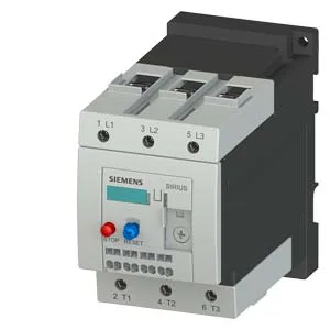
The 3RU1146-4JD1: This is a Siemens SIRIUS thermal overload relay, Size S3, designed to protect motors against overload and phase failure by monitoring the current drawn and tripping the contactor when the thermal model reaches the limit defined by Trip Class 10. It mounts as a standalone unit in the control panel, with a vertical mounting surface that allows +/-135° rotation and +/-45° tilt front-to-back, giving flexibility in enclosure layout.
Trip Class 10 means the relay must trip within 10 seconds at 7.2× the set current — standard for standard-duty motor starting where the acceleration time is under 10 seconds. For longer ramp times (e.g., high-inertia loads), a Class 20 or 30 relay would be needed to avoid nuisance trips during start. The auxiliary contact ratings cover multiple control voltages: 1 A at 24 V, 3 A at 120 V, 2 A at 230 V, and 1 A at 400 V. The 3 A at 120 V rating is the highest current on the auxiliary side — if your PLC input card or control relay draws more than 3 A at 120 V, you need an interposing relay. The 0.22 A at 110/125 V and 0.11 A at 220 V ratings are for lower-power signal circuits. Per-pole power dissipation is 5.7 W. For a three-phase motor, that is 17.1 W total heat to manage inside the enclosure. Shock resistance is 8g for 10 ms, enough for most machine-mounted panels but not for high-vibration applications like crushers or engine-driven generators without additional damping. The relay carries ATEX protection type DMT 98 ATEX G 001, meaning it is approved for use in potentially explosive gas atmospheres (Group II, Category 2G) when installed in the appropriate enclosure. This is a differentiator versus standard overload relays — if the line is in a Zone 1 or Zone 2 area, this part keeps the panel compliant without an additional isolating interface.
The 100% relative humidity rating during operation means it can be used in condensing environments (e.g., washdown areas) as long as the IP20 front protection is adequate — the front is finger-safe but not water-sealed, so it must be inside a cabinet with at least IP54 ingress protection if water spray is present. This allows zero-gap stacking vertically and only 6 mm side spacing, which is tight for heat dissipation — the 5.7 W per pole must be considered when packing multiple relays side by side. Wire sizes: solid conductors 2x (0.5 to 2.5 mm²) for auxiliary contacts; stranded conductors 2x (10 to 50 mm²) and 10 to 70 mm² for the main circuit. For AWG, auxiliary contacts accept 2x (20 to 14). The main circuit terminals are sized for the S3 frame — typically up to 70 mm² stranded, which covers motor feeds up to about 150 A depending on cable type.
For Type 1 coordination (relay may be damaged but no hazard to personnel), gG 200 A is required. These values define the maximum short-circuit current the relay can withstand with the specified fuse — important for the SCCR declaration on the panel nameplate.
Compliance Documentation
The substance prohibition date of 07/01/2006 aligns with the original EU RoHS directive (RoHS 1) effective July 1, 2006. The reference code according to IEC 81346-2 is F (protective device). The ATEX certificate DMT 98 ATEX G 001 is the primary compliance document for explosive atmospheres; additional declarations (CE, UKCA, EAC) are typically bundled with the product documentation from Siemens. No UL or CSA mark is listed in the evidence — verify with the order desk if UL recognition is required for your jurisdiction.