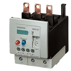
The IP20 front protection keeps live parts behind the panel door; the relay itself is rated for stand-alone installation on a vertical mounting surface, rotatable ±135° and tiltable ±45° front-to-back, giving panel builders flexibility in tight enclosures.
The main circuit uses screw-type terminals accepting stranded wire from 10 to 70 mm² (2x 10–50 mm²). For auxiliary and control circuits, Cage Clamp terminals accept 2x (0.5–2.5 mm²) solid or 2x (20–14 AWG). The auxiliary contact ratings are given per voltage: 1 A at 24 V, 3 A at 120 V, 2 A at 230 V, 1 A at 400 V — these are the maximum switching currents for the built-in N/O and N/C contacts, so check your control voltage before committing the BOM line. Short-circuit coordination is specified for two scenarios: with type of assignment 2 (no damage to the relay after a fault), a gG fuse rated 160 A is required; with type of coordination 1 (relay may need replacement after fault), a 250 A gG fuse is permitted. This matters for selectivity studies — the 160 A limit under assignment 2 is the tighter constraint for upstream breaker sizing. Power dissipation per pole is 6.3 W, so three poles dissipate about 19 W inside the enclosure. Factor that into your thermal budget, especially if the relay is grouped with other heat sources in a sealed cabinet. Surge voltage resistance is rated at 8 kV, and shock resistance at 8g for 10 ms — the relay can handle typical industrial electrical transients and mechanical vibration from contactors or motor starts without nuisance tripping. Storage and transport range extends to -55 to +80 °C. The ATEX certification (DMT 98 ATEX G 001) allows use in potentially explosive gas atmospheres — check the specific zone and gas group against your installation.
The relay measures 70 mm wide, 120 mm high, and 140 mm deep. This means it can be mounted flush against adjacent devices on three sides, with only a 6 mm side gap needed — useful for dense DIN-rail or backplate layouts.