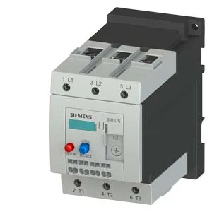
Siemens 3RU1146-4LD1 — Overload Relays

Siemens 3RU1146-4LD1 SIRIUS Thermal Overload Relay, Class 10

MPN3RU1146-4LD1

Siemens SIRIUS 3RU1146-4LD1 thermal overload relay, size S3, Class 10 trip, screw-type main terminals, IP20 front, ATEX certified.

Source DocumentedChannel stated on listing & quote
Condition PhotosReal unit photos / video on request
WhatsApp AnswersFast human replies for machine-down parts
Worldwide DispatchDHL/FedEx — transit quoted per order
Independent China distributor & sourcing agent· Listing updated Sep 2026

Specifications

3RU1146-4LD1 — Identification
ParameterValue
Product brand nameSIRIUS
Product designationthermal overload relay
Frame size (overload relay)S3
Combinable contactor sizesS3
Reference code (IEC 81346-2)F
3RU1146-4LD1 — Protection & Trip
ParameterValue
Overload current setting range70 ... 90 A
Trip classCLASS 10
3RU1146-4LD1 — Electrical (main circuit)
ParameterValue
Poles (main circuit)3
Rated insulation voltage (AC, pollution degree 3)1 000 V
Rated surge withstand voltage8 kV
Main current circuitscrew-type terminals
Power loss at rated current (hot)21 W
Per pole7 W
3RU1146-4LD1 — Auxiliary contacts
ParameterValue
Auxiliary contacts: NO1
Auxiliary contacts: NC1
Auxiliary contacts: CO (changeover)0
Auxiliary switch short-circuit protection (required fuse)fuse gL/gG: 6 A, quick: 10 A
Switching current at 24 V1 A
Switching current at 110 V0.22 A
Switching current at 120 V3 A
Switching current at 125 V0.22 A
Switching current at 220 V0.11 A
Switching current at 230 V2 A
Switching current at 400 V1 A
3RU1146-4LD1 — Connection & Mounting
ParameterValue
Mounting / fastening methodstand-alone installation
Mounting positionwith vertical mounting surface +/-135° rotatable, with vertical mounting surface +/- 45° tiltable to the front and back
Auxiliary/control circuit connection typeCage Clamp terminals
Removable aux./control terminalNo
Conductor cross-section: solid2x (0.5 ... 2.5 mm²)
Conductor cross-section: finely stranded with ferrule2x (0.5 ... 1.5 mm²)
3RU1146-4LD1 — Environmental
ParameterValue
Operating temperature-20 ... +70 °C
Storage temperature-55 ... +80 °C
Transport temperature-55 ... +80 °C
Relative humidity, operating100 %
Max. installation altitude2 000 m
Shock resistance8g / 10 ms
3RU1146-4LD1 — Mechanical
ParameterValue
Width70 mm
Height120 mm
Depth140 mm
3RU1146-4LD1 — Specifications
ParameterValue
Type Of ProtectionDMT 98 ATEX G 001

Product details

The relay dissipates 7 W per pole under load, so the enclosure's internal temperature rise needs to account for that heat — especially when grouping multiple relays in a compact panel. Auxiliary contact ratings are given for multiple control voltages: 1 A at 24 V, 3 A at 120 V, 2 A at 230 V, and 1 A at 400 V. These are the switching capacities for the built-in N/C and N/O contacts that signal the contactor coil or PLC input. The 400 V / 1 A rating confirms it can switch a 400 VAC control circuit directly. Surge voltage resistance is rated at 8 kV, which aligns with IEC 60947-1 overvoltage category III for industrial environments — meaning it withstands switching transients on a 400 V supply without flashover. The relay itself is not intended for washdown areas; it lives inside a panel.

Mounting is stand-alone, not DIN-rail snap-on. Clearance distances are specified: 0 mm upwards, forwards, backwards, and downwards, but 6 mm to the side — so side-by-side mounting is possible with a 6 mm gap. Dimensions are 120 mm high, 70 mm wide, and 140 mm deep. That depth includes the screw-type main terminals and the cage-clamp auxiliary terminals. The main circuit accepts solid or stranded conductors: 2× (0.5…2.5 mm²) for the auxiliary circuit, and 2× (10…50 mm²) or single 10…70 mm² for the main circuit. AWG equivalents for the auxiliary contacts are 2× (20…14).

Coordination and fusing

For Type 1 coordination (no damage to the relay under fault, but may need replacement), a gG fuse of 250 A is required upstream. For Type 2 coordination (relay remains functional after a fault), the fuse drops to 160 A gG. These values guide the upstream protection selection in the motor branch circuit.

Environmental limits

Relative humidity tolerance is 100%, so condensation inside a non-condensing enclosure is acceptable. Shock resistance is 8g for 10 ms, typical for industrial panel-mounted gear.

Frequently asked questions

What compliance documentation does this relay carry?

It is RoHS compliant with a substance prohibitance date of 07/01/2006, and it holds ATEX certification DMT 98 ATEX G 001 for use in explosive atmospheres. The reference code per IEC 81346-2 is F (protective device).

What are the key ratings for the auxiliary contacts?

The auxiliary contacts are rated 1 A at 24 V, 3 A at 120 V, 2 A at 230 V, and 1 A at 400 V. These are the switching capacities for the built-in N/C and N/O signaling contacts.

What is the trip class and what does it mean?

It is Class 10, meaning the relay will trip within 10 seconds at 7.2× the current setting. This matches the thermal protection curve for standard AC induction motors during a locked-rotor condition.

What are the mounting clearances?

Clearances are 0 mm upwards, forwards, backwards, and downwards, with 6 mm required to the side. The relay can be mounted on a vertical surface and rotated ±135° or tilted ±45°.

MPN
3RU1146-4LD1