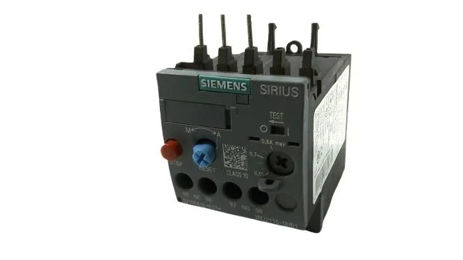
The Siemens 3RU2116-0HB1 is a SIRIUS thermal overload relay in the S00 frame size, CLASS 10 device. Rated for 690 V, the relay handles the full voltage range common in industrial three-phase networks up to that line-to-line maximum. The M3 main contact screws accept 2× (0.5 to 1.5 mm²) or 2× (0.75 to 2.5 mm²) solid or stranded wire — sized for the control panel's typical motor branch circuit.
The CLASS 10 trip characteristic is the key selection parameter: it coordinates with contactors and motor starters so that the relay opens before the motor winding reaches damaging temperature during a locked-rotor event. For conveyors and material-handling drives with normal acceleration profiles (not high-inertia loads), CLASS 10 is the standard choice. Temperature compensation is active from -40 to +60 °C, meaning the trip curve stays accurate across the panel's ambient range without manual adjustment. The auxiliary contact ratings cover common control voltages: 2 A at 24 V, 2 A at 230 V, 1 A at 400 V, and 0.75 A at 690 V. These are the switching capacities for the trip-indication circuit — useful for feeding a PLC input or a remote alarm lamp. Power dissipation per pole is 1.6 W, so three poles total 4.8 W at rated current.
Integration Notes
The 3RU2116-0HB1 is a stand-alone mount — it installs independently on the mounting plate or DIN rail. Verify the panel layout accommodates the 45 mm width and 80 mm depth. Screw terminals for the main circuit use a Pozidriv PZ2 tip with a 5–6 mm shaft diameter. The auxiliary switch is integrated, so no separate terminal block is needed for the trip signal. Wire range: 2× (0.5 to 1.5 mm²) or 2× (0.75 to 2.5 mm²) solid or stranded. Mounting position is any orientation. MTTF with high demand rate is 2,280 years.