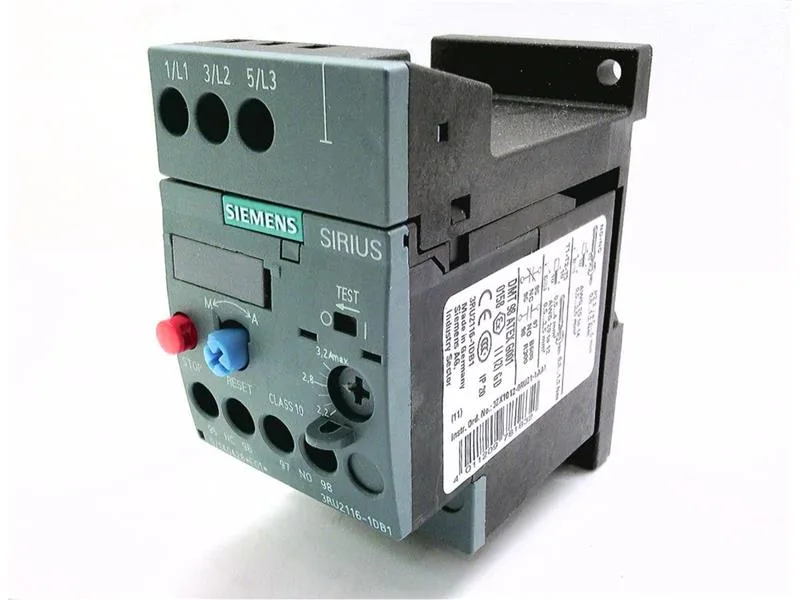
Rated for 690 V and 400 V switching at 1 A (AC-3e), this relay handles motor circuits up to 1.1 kW at 400 V and 2.2 kW at 690 V. The auxiliary switch is integrated, and a mechanical flag gives a visual "Tripped" message — no separate aux block needed for that status signal. Mounting position is any, and it's designed for stand-alone installation with screw-type terminals. It's a DIN-rail-mount part that clips into the standard S00 contactor footprint — common in motor control centers and distribution panels.
The trip class (Class 10) is the critical selection parameter: it determines how long the relay can carry a locked-rotor current before opening. For a motor that accelerates in under 10 seconds, this relay won't false-trip on startup. If your motor has a longer acceleration (high-inertia loads like fans or centrifuges), you'd need a Class 20 or 30 relay instead. The 45 mm width and 89 mm height (80 mm depth) mean it fits in tight panel layouts without needing extra side clearance. Temperature compensation is active from -40 to +60 °C, so the trip curve stays accurate whether the panel is in a cold warehouse or a hot machine room. The auxiliary contact ratings cover both control and indication: at 24 V it switches 2 A, at 230 V it switches 2 A, and at 400 V it switches 1 A.
The 3RU2116-1DB1 is the direct thermal overload relay companion for the S00 contactor range. If you're replacing a failed unit in an existing panel, the wiring pattern and mounting footprint are standard for the S00 family — no panel modification needed.
Wiring and installation notes
Terminals accept 2× (0.5 to 1.5 mm²) or 2× (0.75 to 2.5 mm²) solid or stranded wire. Screw terminals use Pozidriv PZ2 with a 5-6 mm shaft diameter — common bits in any electrician's kit. Wire strip length is standard for the terminal design; no special tooling required. The auxiliary switch is integrated into the relay housing, so there's no separate add-on block to order for the "Tripped" signal. That saves a catalog line and a wiring step on the panel build.