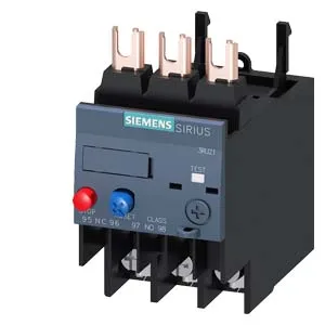
What This Relay Does on the Line
Rated for main circuits up to 690 V, it handles 18.5 kW at 400 V, 22 kW at 500 V, and 37 kW at 690 V. The 480 V and 600 V ratings both list 40 A, so it covers North American 480Y/277 V and 600 V delta systems cleanly. The built-in auxiliary switch provides status feedback — a tripped message is signaled on the auxiliary contact set, which is what the "Note for message 'Tripped'" spec refers to. This lets a PLC or annunciator panel see the relay state without extra hardware.
Mounting and Wiring in the Panel
Mounts directly onto a contactor (contactor mounting), in any position. The S0 footprint is 45 mm wide by 85 mm deep — fits standard DIN-rail enclosures without overhang. Main circuit connections use ring cable lugs with M4 screws; auxiliary connections use Pozidriv PZ2 screwdriver tips, 5–6 mm shaft diameter. Temperature compensation is active from -40 to +60 °C, so the trip curve stays accurate even in hot enclosures or cold outdoor installations.
The integrated auxiliary switch is rated for both AC and DC control circuits. At 24 V DC it switches 2 A; at 120 V AC it switches 3 A; at 230 V AC it switches 2 A; at 400 V AC it handles 1 A. For DC applications at higher voltages, derate to 0.3 A at 60 V, 0.22 A at 110/125 V, and 0.11 A at 220 V. These are the maximum breaking currents — your PLC output card or relay coil must stay within these limits. Per-pole power dissipation is 3.2 W. In a dense panel with multiple relays, factor this into the thermal budget — the S0 frame dissipates heat through the contactor base, so keep airflow around the mounting rail.